For my final year project I ended up experimenting with ATxmega16e5 microcontroller, after major step backs with TI ARM microprocessors (don't get me wrong ARM is very powerful).
At the first glance these new xmega series uC are quite impressive. 32MHz internal clock, incredibly fast ADC (16e5 can have up to 300ksps), 12 bit adc, DAC, two or more USARTs and list goes on. Moreover you are able to use tools you're familiar with, when it comes to program AVR family micros, providing you have programmed AVR family before. I have yet to test full capabilites of the new xmega series, but I'll write posts about individual modules, like ADC, USART, DAC etc.
Before I dive into breakout board, I want to mention that xmega series are powered 3.3V ONLY, even input voltage levels need to be 3.3V, I already destroyed two of my chips by accidently passing input of 5V. Also, xmega is programmed with PDI instead of the usual ISP. Even though I didn't convert my usbasp to support PDI, I think I'll be able to give some guidlines later on, so you can avoid burning your micro.
Breakout
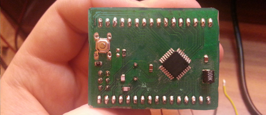
First thing to do, is to make a breakout board for the new xmega micro. I tried to follow some guidlines from official atmel circuit guidlines, even though it is very similar to what we already know from mega series.
I have to warn you, the breakout board doesn't have any voltage regulator, or any protection for the pins. It is very simple, just so I'll be able to boot the micro and program it.
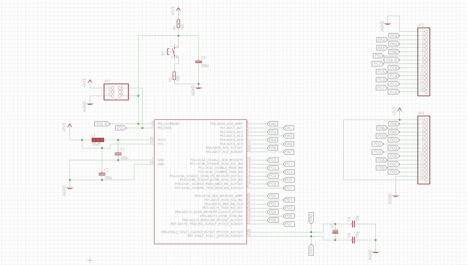
Breakout board circuit schematic:
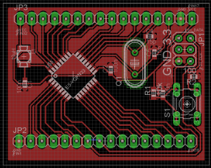
PCB design:
Download: ATxmega16e5breakout.zip (52.29K)
Note: if you don't have the GND mask filled, press ratnest test in Eagle, it should appear.
Converting USBASP to support PDI
As I mentioned before, I didn't go through with this, but I did try. Later I'll verify whether what I'm saying is true or not. But I do want to mention what you absolutly shouldn't do!
Probably you've already encountered this blog http://szulat.blogspot.co.uk/2012/08/atxmega-programmer-for-050.html
It says if you have 3.3V usbasp, that the circuit would be more simple. And I blindly believed it. He might be correct, but I didn't check the chinese USBASP's circuit. Basically, by setting the USBASP to 3.3V mode I only switch the ISP VCC output to 3.3V, NOT the logic levels. The logic HIGH is still 5V. From frustration, to see whether I'm sending any data I put my oscilloscope to the PDI_DATA pin, and observed that I was sending data in 5V
In addition, according to this russian blog: http://service4u.narod.ru/html/atxmega_avrdude.html you don't need to update the firmware of the USBASP, or recompile the avrdude. Just download the latest avrdude and it should work out of the box. I did notice that latest AVRDUDE even had xmega16e5 inside it's conf file.
Recap
1. Use the following schematic, including for chinese 3.3V supported USBASPs
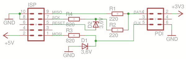
Source: http://szulat.blogspot.co.uk/2012/08/atxmega-programmer-for-050.html
2. Update to the latest AVRDUDE
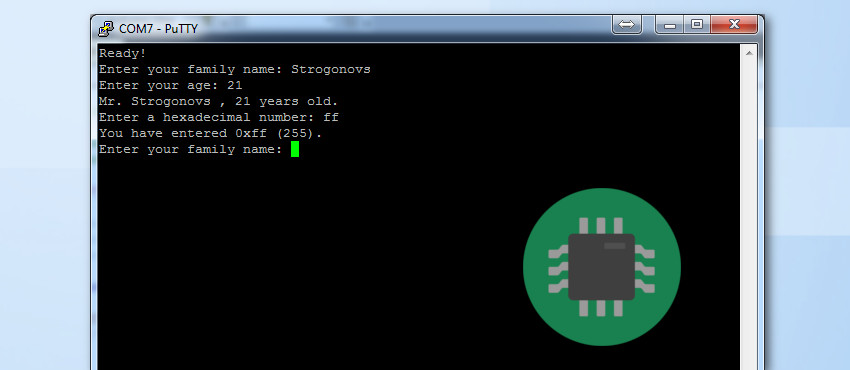
3. Program your xmega with some test code
#define F_CPU 2000000UL

#include <avr/io.h>
#include <util/delay.h>

int main(void)
{
    PORTA_DIR = 0xFF;
    while(1)
    {
        PORTA_OUT = ~PORTA_OUT;
       _delay_ms(10);
    }
}
References
Henri Keinonen. (2013). Programming xmega with usbasp & avrdude. Available: http://ketturi.kapsi.fi/2013/05/programming-xmega-with-usbasp-avrdude/. Last accessed 08/03/2014.
NA. (2013). Как прошить XMEGA при помощи USBASP программатора. Available: http://service4u.narod.ru/html/atxmega_avrdude.html. Last accessed 08/03/2014.
szu. (2012). ATxmega programmer for $0.50 . Available: http://szulat.blogspot.co.uk/2012/08/atxmega-programmer-for-050.html. Last accessed 08/03/2014.
Atmel. (2013). Atmel AT01080: XMEGA E Schematic Checklist . Available: http://www.atmel.com/Images/Atmel-42087-XMEGA-E-Schematic-Checklist_Application-Note_AT01080.pdf. Last accessed 08/03/2014.