For most of the people probably the next step in the world of MEMS is to interface gyroscope. Most likely use gyroscope data to fuse with accelerometer data. If you have implanted acc before, you’ll know that acc is very responsive and noisy when it comes to measuring pitch and roll. It is possible to smooth out the data via sensor fusion. In this tutorial I will explain what data we will be getting from gyroscope, how to use the data to calculate pitch, roll and yaw and finally how to fuse sensor data with complimentary filter.
What is gyroscope?
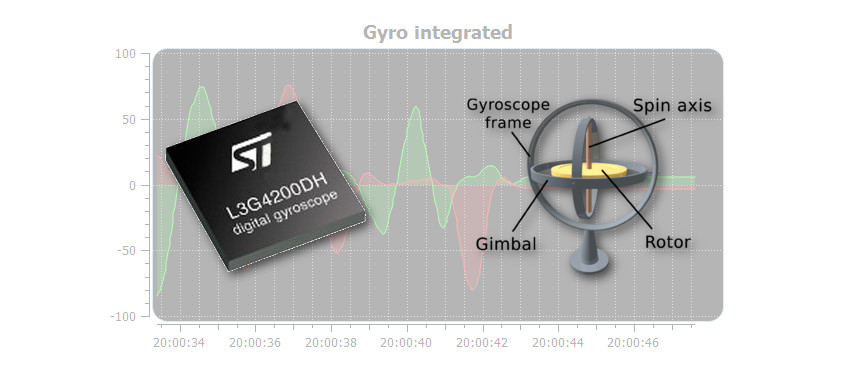
First of all, gyroscopes are used for maintaining or measuring orientation. A mechanical gyroscope typically consists of a spinning disc, where the axes it connected to are able to move freely in any orientation. A MEMS gyro is very similar, but instead of spinning disc it consists of some sort of vibrating resonator. The idea is the same; a vibrating object tends to continue vibrating in the same plane as its support rotates.
In most cases, a MEMS gyroscope will measure the angular velocity (probably degrees per second), from which you can calculate the angle; I’ll elaborate on that as we go on in this article.
Initializing L3G4200D
Just like in the previous article about ADXL345 I’ll be using I2C protocol to communicate with the gyroscope. I assume, you’re familiar with this protocol, if not, then it would be probably wise to do some background reading on I2C and then come back later.
I won’t go in a lot of details about how to initialize every aspect of gyro, but enough to get you started.
Basically, to initialize the L3G4200D, you just have to configure one register CTRL_REG1 (see tables below). In this register you can enable axis for reading and set the output data rate.
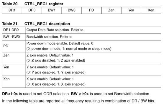
n our case, we will just leave the ODR as it is, and only enable all axes. Also, for simplicity we will configure the device’s power down mode to “normal node”. Taking into account our preferences we would need to write 0x0F to the CTRL_REG1 register.
However, to avoid data corruption when reading the data from L3G4200D, we should enable “Block Data Update” in CTRL_REG4 (see table below). You could technically, check whether an overrun occurred in STATUS_REG as well. But for simplicity, by enabling BDU, it won’t overrun the data until both MSB and LSB is read from the corresponding axis output registers.
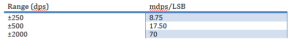
In the same register, we can specify the measurement range and sensitivity of the gyro by changing FS1 and FS0 bits.
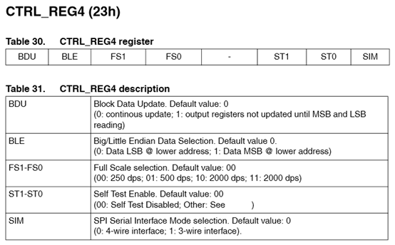
In my case I want the sensitivity to be as high as possible, so I’ll set the measurement range to 250 dps. Lower measurement range will give you higher accuracy (see table below). By taking all the preferences into account, we need to write 0x80 in register CTRL_REG4.
One final thing, normally we would like to initialize the offset as well. However, in comparison with the accelerometer ADXL345 this gyro doesn’t have a hardware offset. So only option we have is a software offset.
Finally, your initialization should look something like this:
void L3G4200D::init(double xoffset, double yoffset, double zoffset)
{
  _xoffset = xoffset;
  _yoffset = yoffset;
  _zoffset = zoffset;

  writeTo(L3G4200D_CTRL_REG1, 0x0F);
  writeTo(L3G4200D_CTRL_REG4, 0x80); //Dont override values
}
Reading the raw angular velocity and converting to dps
At this point we are ready to read the data from the gyro. The angular velocity is stored in 6 registers: OUT_X_L, OUT_X_H, OUT_Y_L, OUT_Y_H, OUT_Z_L and OUT_Z_H.
Just like with accelerometer ADXL345 the results are divided in two 8 bit registers forming 16 bit registers where the format is LSB first then followed by MSB. The data are stored in two’s compliment format. With I2C protocol, it is possible to request multiple bytes in one reading session. Note, in case of L3G4200D gyro, to read the data sequentially, you must alter slightly the initial address from which you want to read. Nothing special you just have to set first bit in the address to logic HIGH. So to read the data from this gyro you have to provide the address of OUT_X_L register ORed with 0x80 and request 6 bytes.
After we have read raw data from the gyroscope, we need to convert them to dps. Basically, we just how to multiply the raw data with a pre-calculated constant, which changes according to your “Range” settings.
In my case, I’m using ±250dps mode, which gives me 8.75 mdps/LSB. So that means I’ve to multiply the data with 0.00875 to convert the raw data to dps. See the table above for constants according to your settings.
See the code below on how I’m reading and converting the gyroscope raw data to dps:
GyroDPS L3G4200D::readGyroDPS()
{
  //deafult 250dps = 8.75 mdps/digit

  GyroRaw raw;
  raw = readGyro();

  double fXg, fYg, fZg;
  fXg = raw.x * 0.00875 + _xoffset;
  fYg = raw.y * 0.00875 + _yoffset;
  fZg = raw.z * 0.00875 + _zoffset;

  GyroDPS dps;

  dps.x = fXg * ALPHA_G + (xg * (1.0-ALPHA_G));
  xg = dps.x;

  dps.y = fYg * ALPHA_G + (yg * (1.0-ALPHA_G));
  yg = dps.y;

  dps.z = fZg * ALPHA_G + (zg * (1.0-ALPHA_G));
  zg = dps.z;

  return dps;


}

GyroRaw L3G4200D::readGyro()
{
  readFrom(L3G4200D_OUT_X_L | 0x80, L3G4200D_BYTES_READ, _buff); //0x80 enable auto increment (who would have known?)

  // each axis reading comes in 16 bit resolution, ie 2 bytes. Least Significat Byte first!!
  // thus we are converting both bytes in to one int
  GyroRaw raw;

  raw.x = (((int)_buff[1]) << 8) | _buff[0];
  raw.y = (((int)_buff[3]) << 8) | _buff[2];
  raw.z = (((int)_buff[5]) << 8) | _buff[4];

  return raw;
}
Just as it was with accelroemeter, I’ve implemented a simple low pass filter in the readGyroDPS() method as well:
Calculating pitch, roll and yaw
Calculating distance traveled via simple integration
At this point we are ready to convert the data coming from gyro into some more useful information. Remember high school physics, that distance is just integration of velocity:
\(s_n = s_{n-1} + vt\)
The idea is that if you take measurements from gyro in constant interval, you can get some estimation of the distance. However, because we can’t take infinite amount of measurements from the gyro, our integral will only be estimation, and it will drift inevitably.
It is important to consider that gyroscope has limited refresh rate as well. In my case, I set the data rate to 100Hz, which is the default one. Which basically means, that gyro will produce new data every 10ms. If we read faster than that, most likely we will get old data, or even worse, we will get corrupted data.
Like with any problem, there are multiple solutions, but I personally like to use a timer to raise a flag every 10ms. It is important to remember, that interrupt routines should be as short as possible, to reduce the delay for the main cycle and other ISRs. And I2C by all means is not something you would want to implement directly in ISR. In its nature this protocol is quite slow. And I’ve tested, that it doesn’t work in Arduino, it looks like it has some concurrency issues with other ISRs.
Anyway as I mentioned before I like to signal the main routine that it is time to read gyro via simple Boolean flag. However, just by raising the flag and calculating the new distance will give you a huge error (see picture below). It drifts so quickly, because the time difference dT is not exactly 10ms, since we raised the flag. Before our code got to compute the orientation, the dT increased enough to produce a huge error. To reduce the error, I’d suggest measuring the dT between previous and current measurements. Like this we slightly improve the estimation of the distance.
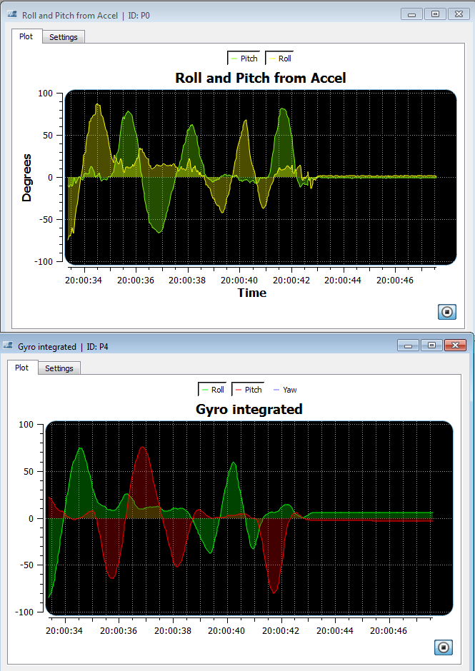
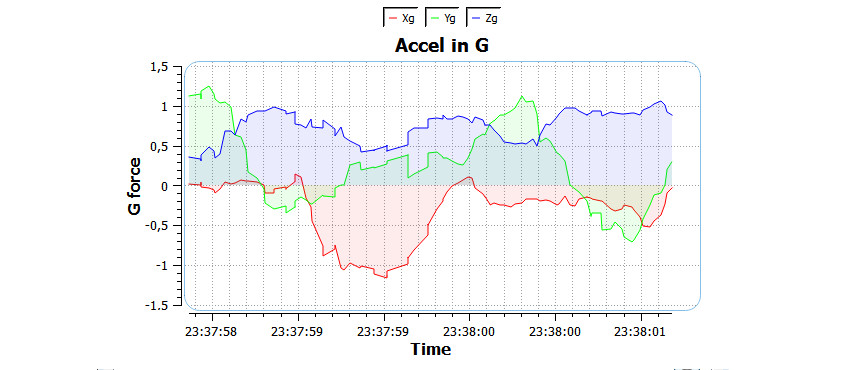
In these two plots you can easily compare how reactive an accelerometer is and how smooth the gyro readings are. Also, you should be able to notice that around 20:00:43, I placed the sensor back in it original orientation, while accel is reading the roll to be around 0, our calculations from gyro gives us 5.7°. As already mentioned previously, that is because of the estimation of the integral.
Code for implementing simple estimation of orientation:
Note, that I used timer 1 library provided by Arduino.
//Gyro sampling rate in micro seconds
#define SampleRate 10000
L3G4200D gyro;
bool readGyro;
double xi,yi,zi;
void setup()
{

  Serial.begin(115200);

  Serial.println("Ready.");
  Wire.begin();
  gyro.init(-0.18891-0.04382, -0.09454-0.05530, -0.31720-0.04951); //Don’t  use my calibration values
  pT = 0;
   xi = yi = zi = 0;
  readGyro = false;
  Timer1.initialize(SampleRate);
   Timer1.attachInterrupt( timerIsr );
}
void timerIsr()
{
  readGyro = true;
}
void loop()
{
//GYRO
  if(readGyro)
  {
    readGyro = false;
    unsigned long cT = micros();

    GyroDPS gDPS;
    gDPS = gyro.readGyroDPS();

    unsigned long dT = cT - pT;
    pT = cT;

    Serial.print("{P2|X|255,0,0|");
    Serial.print(gDPS.x);


    Serial.print("|Y|0,255,0|");
    Serial.print(gDPS.y);

    Serial.print("|Z|0,0,255|");
    Serial.print(gDPS.z);
    Serial.println("}");


    Serial.print("{P4|Roll|0,255,0|");
    xi = xi + gDPS.x*(dT/1000000.0);
    Serial.print(xi);
    yi = yi + gDPS.y*(dT/1000000.0);
    Serial.print("|Pitch|255,0,0|");
    Serial.print(yi);

    zi = zi + gDPS.z*(dT/1000000.0);
    Serial.print("|Yaw|100,100,255|");
    Serial.print(zi);
    Serial.println("}");

  }
  //END GYRO
}
Fusing accelerometer data with gyroscope data
As you should have noticed in the plots above, gyroscope has very smooth reading but has a drift. Accel, on the other hand is very noisy, but zero drift. Wouldn’t it be cool, if we could fuse those two sensor readings to form a more accurate reading of the real world? There are two main stream approaches to this problem:
- Kalman filter
- complementary filter
Initially I thought of explaining kalman filter in this article, but after studying it more thoroughly myself, I understood, that it is not something I can quickly introduce. Kalman filter deserves an article on its own. I’ll do my best to write one, especially about discrete kalman filter in the next month or so.
In the mean time, a very easy substitute for kalman filter, which I would argue, works almost as good as Kalman filter is complementary filter. It is much simpler filter nonetheless, for sure more intuitive.
The idea of complementary filter is, you set proporations of how much you trust a corresponding data, and sum the results together. A general formula would be something like this:
\(\text{Fused sensor} = 0.70 * S_1 + 0.25 * S_2 + 0.05 * S_3\)
Where 0.7, 0.25 and 0.05 is the ratios of how much you trust a corresponding sensor data. The lower the ratio, the less you trust it. Note that the total sum of ratios has to be 1.0.
In the case of fusing accel data with gyro estimation, we set the ratios to be 0.95 for gyro and 0.05 for accel. It could probably go even lower than 0.05, 0.01 might be even better for accel. The reason for this is that we want to have just enough sensor fusion with the gyro to stop it drifting. Gyro already is very smooth and rather accurate.
In the code it would look something like this:
angleF_roll = 0.95*(angleF_roll + gDPS.x*(dT/1000000.0)) +0.05*accelRot.roll;
angleF_pitch = 0.95*(angleF_pitch - gDPS.y*(dT/1000000.0)) +0.05*accelRot.pitch;
You can see results below, note that at the end I returned the device in its initial orientation and complementary filtered gyro+accel orientation estimate is back to 0.
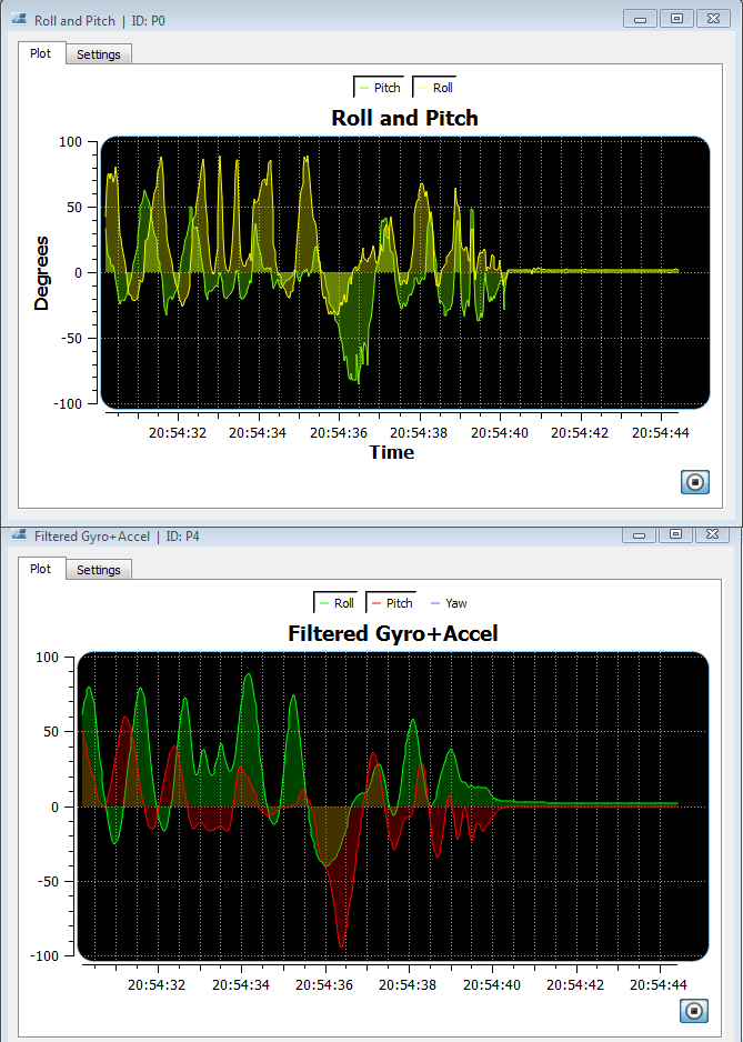
Also note how smooth the gyro+accel data is compared to just accel’s measurements of the pitch and roll. Basically, we took the best of both worlds, the noiseless gyro and the precise accel and fused them together.
Just as a reminder, the code to implement both the gyro and accel should looks something similar to this, providing you followed the previous article about accelerometer implementation:
#include <Wire.h>
#include <TimerOne.h>

#include "ADXL345.h"
#include "L3G4200D.h"
//Gyro sampling rate in micro seconds
#define SampleRate 10000
ADXL345 accel;
L3G4200D gyro;
bool readGyro;
double angleF_roll;
double angleF_pitch;
unsigned long pT; //previous time
void setup()
{

  Serial.begin(115200);

  Serial.println("Ready.");
  Wire.begin();

  accel.init(-1, 0, 8);
  gyro.init(-0.18891-0.04382, -0.09454-0.05530, -0.31720-0.04951);
  accel.setSoftwareOffset(-0.023, 0, 0.03577027);
  //accel.printCalibrationValues(40);
  //gyro.printCalibrationValues(40);


  pT = 0;
   readGyro = false;
   angleF_roll = angleF_pitch = 0;

  Timer1.initialize(SampleRate);
  Timer1.attachInterrupt( timerIsr );
}

void timerIsr()
{
  readGyro = true;
}

void loop()
{

  //ACCEL
  AccelRotation accelRot;

  accelRot = accel.readPitchRoll();
  Serial.print("{P0|Pitch|127,255,0|");
  Serial.print(accelRot.pitch);


  Serial.print("|Roll|255,255,0|");
  Serial.print(accelRot.roll);
  Serial.println("}");


  AccelG accelG;
  accelG = accel.readAccelG();
  Serial.print("{P1|Xg|255,0,0|");
  Serial.print(accelG.x);


  Serial.print("|Yg|0,255,0|");
  Serial.print(accelG.y);

  Serial.print("|Zg|0,0,255|");
  Serial.print(accelG.z);
  Serial.println("}");
  //END ACCEL

//GYRO
  if(readGyro)
  {
    readGyro = false;
    unsigned long cT = micros();

    GyroDPS gDPS;
    gDPS = gyro.readGyroDPS();

    unsigned long dT = cT - pT;
    pT = cT;

    Serial.print("{P2|X|255,0,0|");
    Serial.print(gDPS.x);


    Serial.print("|Y|0,255,0|");
    Serial.print(gDPS.y);

    Serial.print("|Z|0,0,255|");
    Serial.print(gDPS.z);
    Serial.println("}");


    Serial.print("{P4|Roll|0,255,0|");
    angleF_roll = 0.95*(angleF_roll + gDPS.x*(dT/1000000.0)) +0.05*accelRot.roll;
    Serial.print(angleF_roll);
    angleF_pitch = 0.95*(angleF_pitch - gDPS.y*(dT/1000000.0)) +0.05*accelRot.pitch;
    Serial.print("|Pitch|255,0,0|");
    Serial.print(angleF_pitch);
    Serial.println("}");

  }
  //END GYRO
}
L3G4200D.h file
#ifndef L3G4200D_h
#define L3G4200D_h

#include <Wire.h>
#include "Arduino.h"


#define L3G4200D_DEVICE 105
#define L3G4200D_BYTES_READ 6

#define L3G4200D_CTRL_REG1 0x20
#define L3G4200D_CTRL_REG2 0x21
#define L3G4200D_CTRL_REG4 0x23
#define L3G4200D_CTRL_REG5 0x24

#define L3G4200D_OUT_X_L 0x28
#define L3G4200D_OUT_X_H 0x29
#define L3G4200D_OUT_Y_L 0x2A
#define L3G4200D_OUT_Y_H 0x2B
#define L3G4200D_OUT_Z_L 0x2C
#define L3G4200D_OUT_Z_H 0x2D

#define ALPHA_G 0.3

struct GyroRaw
{
  int x;
  int y;
  int z;
};

struct GyroDPS
{
  double x;
  double y;
  double z;
};

class L3G4200D
{
  public:
    L3G4200D();
    void init(double xoffset=0, double yoffset=0, double zoffset=0);
    void writeTo(byte address, byte val);
    void readFrom(byte address, int num, byte _buff[]);
    GyroRaw readGyro();
    GyroDPS readGyroDPS();
    void printAllRegister();
    void print_byte(byte val);
    void printCalibrationValues(int samples);
//    bool checkOverrun();

  private:
     byte _buff[6];

     double xg;
     double yg;
     double zg;

     double _xoffset;
     double _yoffset;
     double _zoffset;


};

#endif
L3G4200D.cpp file
#include "Arduino.h"
#include "L3G4200D.h"

L3G4200D::L3G4200D()
{
  xg = yg = zg = 0;

}

void L3G4200D::init(double xoffset, double yoffset, double zoffset)
{
  _xoffset = xoffset;
  _yoffset = yoffset;
  _zoffset = zoffset;

  writeTo(L3G4200D_CTRL_REG1, 0x0F);
  writeTo(L3G4200D_CTRL_REG4, 0x80); //Dont override values
  writeTo(L3G4200D_CTRL_REG5, 0x80);
}

void L3G4200D::printCalibrationValues(int samples)
{
  double x,y,z;
  double xt,yt,zt;
  xt = 0;
  yt = 0;
  zt = 0;

  Serial.print("Calibration in: 3");
  delay(1000);
  Serial.print(" 2");
  delay(1000);
  Serial.println(" 1");
  delay(1000);

  for(int i=0; i<samples; i++)
  {
    GyroDPS dps = readGyroDPS();
    xt += dps.x;
    yt += dps.y;
    zt += dps.z;
    delay(100);
  }

  Serial.println("Gyro Offset (dps): ");
  Serial.print("X: ");
  Serial.print(xt/float(samples),5);
  Serial.print(" Y: ");
  Serial.print(yt/float(samples),5);
  Serial.print(" Z: ");
  Serial.println( zt/float(samples),5);

  delay(2000);
}

GyroDPS L3G4200D::readGyroDPS()
{
  //deafult 250dps = 8.75 mdps/digit

  GyroRaw raw;
  raw = readGyro();

  double fXg, fYg, fZg;
  fXg = raw.x * 0.00875 + _xoffset;
  fYg = raw.y * 0.00875 + _yoffset;
  fZg = raw.z * 0.00875 + _zoffset;

  GyroDPS dps;

  dps.x = fXg * ALPHA_G + (xg * (1.0-ALPHA_G));
  xg = dps.x;

  dps.y = fYg * ALPHA_G + (yg * (1.0-ALPHA_G));
  yg = dps.y;

  dps.z = fZg * ALPHA_G + (zg * (1.0-ALPHA_G));
  zg = dps.z;

  return dps;


}

GyroRaw L3G4200D::readGyro()
{
  readFrom(L3G4200D_OUT_X_L | 0x80, L3G4200D_BYTES_READ, _buff); //0x80 enable auto increment (who would have known?)

  // each axis reading comes in 16 bit resolution, ie 2 bytes. Least Significat Byte first!!
  // thus we are converting both bytes in to one int
  GyroRaw raw;

  raw.x = (((int)_buff[1]) << 8) | _buff[0];
  raw.y = (((int)_buff[3]) << 8) | _buff[2];
  raw.z = (((int)_buff[5]) << 8) | _buff[4];

  return raw;
}

// Writes val to address register on device
void L3G4200D::writeTo(byte address, byte val)
{
  Wire.beginTransmission(L3G4200D_DEVICE); // start transmission to device
  Wire.write(address); // send register address
  Wire.write(val); // send value to write
  Wire.endTransmission(); // end transmission
}

// Reads num bytes starting from address register on device in to _buff array
void L3G4200D::readFrom(byte address, int num, byte _buff[])
{
  Wire.beginTransmission(L3G4200D_DEVICE); // start transmission to device
  Wire.write(address); // sends address to read from
  Wire.endTransmission(); // end transmission

  Wire.beginTransmission(L3G4200D_DEVICE); // start transmission to device
  Wire.requestFrom(L3G4200D_DEVICE, num); // request 6 bytes from device Registers: DATAX0, DATAX1, DATAY0, DATAY1, DATAZ0, DATAZ1

  int i = 0;
  while(Wire.available()) // device may send less than requested (abnormal)
  {
    _buff[i] = Wire.read(); // receive a byte
    i++;
  }
  if(i != num)
  {

  }
  Wire.endTransmission(); // end transmission
}

void L3G4200D::printAllRegister()
{
    byte _b;
    Serial.print("0x00: ");
        readFrom(0x0F, 1, &_b);
    print_byte(_b);
    Serial.println("");
    int i;
    for (i=32;i<=56;i++)
        {
        Serial.print("0x");
        Serial.print(i, HEX);
        Serial.print(": ");
        readFrom(i, 1, &_b);
        print_byte(_b);
        Serial.println("");
    }
}

void L3G4200D::print_byte(byte val)
{
    int i;
    Serial.print("B");
    for(i=7; i>=0; i--){
        Serial.print(val >> i & 1, BIN);
    }
}
If you’re careful reader, you should have noticed, that after fusing accel with gyro, we are not measuring yaw anymore. Obviously accelerometer can’t measure yaw, to avoid yaw drifting, we have to use another sensor – magnetometer. In part 3 I’ll be explaining how to interface magnetometer, calculate heading, fusing the data with gyro and finally calculating tilt compensated heading.
Download: L3G4200D.zip (1.98K)
References
ST. (2010). L3G4200D. Available: http://www.forkrobotics.com/wp-content/uploads/2013/05/L3G4200D.pdf. Last accessed 16.06.2014.
bildr. (2011). L3G4200D Tripple Axis Gyroscope + Arduino. Available: http://bildr.org/2011/06/l3g4200d-arduino/. Last accessed 16.06.2014.