For my group design project one of the main tasks was to determine the amount Lego blocks stacked together. The group gave me this task, so I decided to make a weight sensor based on strain gauge. Hopefully I'll be able to briefly explain how it is done and what obstacles I had to overcome.
Warning: the article turned out to be rather large
Hopefully, it will help someone out there in the world to get over frustation faster, when working with strain gauges.
Thanks hackaday for publishing my article!
http://hackaday.com/2013/06/12/building-a-digital-scale-from-scratch/
Strain Gauge
Introduction
Strain gauges are sensors which are used in variety of physical measurements. They change resistance when they are stretched or compressed. Because of this property, strain gauges often are bonded to a solid surface and used for measuring acceleration, pressure, tension and force. We can use the measurement of tension to determine the weight applied to the load cell. Fundamentally, strain is a change in length per unit length. For instance, if a 1 m long beam is stretched to 1.000002 m, the strain is 2 micro strains. One characteristic of strain gauges are gauge factor, and is defined as fractional change in resistance divided by the strain. For example, if we have strain gauge with gauge factor of 2, for the previous example the resistance change would be (2*2)*10^-6 =4*10^-6 => 4μΩ. Normally strain gauge resistance value are around 120 – 350 Ω, however there are some gauges with resistance as low as 30Ω or as high as 3kΩ
Strain gauge inner workings
|
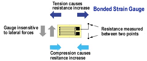
Figure 1 Common strain gauge |
If a strip of conductive metal is stretched, it will become skinnier and longer, which will result an increasing electrical resistance. On the contrary, if you compress the strain gauge, it will broaden and shorten, hence the electrical resistance will decrease. If these stretches don’t exceed strain gauge’s elasticity, the strip can be used for measuring weight. A typical strain gauge would look something like this:
Wheatstone bridge (measuring resistance)
Because the change of resistance is very small, it’s a little bit trickier than just measuring resistance between two points. As stated above, the change can be in micro-ohms. So we have to find a way to measure these small changes. Commonly, used circuit for sensitive resistance measurements is Wheatstone bridge (Figure 2). This circuit is commonly used for converting the micro-strains into voltage changes, that can be then fed into ADC pin in micro-controller. Essentially, Wheatstone bridge is four resistors connected in a square. When the bridge is perfectly balanced the output voltage would be 0, but if one of the resistors slightly changes, the bridge produces significant measurable voltage. Still the Vout would be in mV, I will expand on that later. When used with a strain gauge, one of the resistors in the bridge will be replaced by the sensor and when the strain gauge undergoes dimensional changes, it will unbalance the Wheatstone bridge proportional to the strain
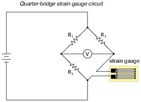
Figure 2 Wheatstone bridge
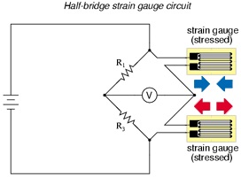
Figure 3 Half bridge circuit with temperature compensation
In Figure 2 you can see Quarter Wheatstone bridge, which has only one resistor replaced by the strain gauge. Typically, the resistors R1, R2, R3 are the same as unstrained resistance of strain gauge. One thing we have to remember when using strain gauge, the wire resistance plays significant role when balancing this bridge. Because, as stated above, the changes are in micro-ohms, and wire resistance can influence the results. This circuit can be used for weight sensing, but it has one significant problem, the strain gauges resistance varies in different temperatures. For our case, we might be able to compensate that in software, because our error of margin can be up to 5 g. If we are not able to compensate for the temperature, we can use half-bridge circuit (Figure 3). Essentially, we have strain gauge on top and on the bottom of the beam, and if temperature changes, one of the strain gauges will compress the other stretched, which will automatically balance the bridge. This is a very common practice when making scales with strain gauges.
To gain greater sensitivity, the best practice would be to use full-bridge circuit (Figure 4), which has all the resistors as strain gauges. This type of bridge is often used, if it is not possible to balance the strains measured in the half-bridge. Another advantage of full-bridge is that because all the resistors are measuring strain the result will not be approximation of strain like for Quarter-bridge or half-bridge, but it will be directly proportional to the force applied on the beam.
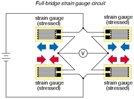
Figure 4 Full-bridge circuit
Choosing a material for the beam
Since strain gauge’s linearity is highly dependent on the material it’s applied to, we have to research materials commonly used in weight measurements or materials which have a reasonably linear strain vs. force curve.
We found out the most common material used in making of load cell is aluminium, because of its linearity and basically no change visual deformation when it’s stressed.
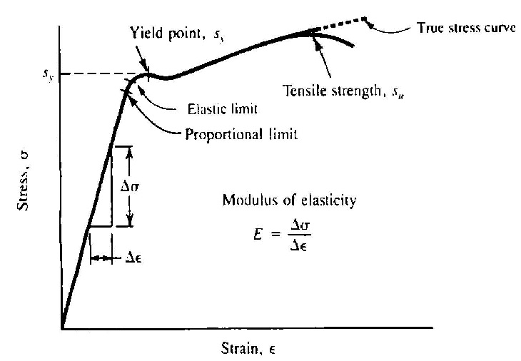 Typical aluminium stress vs. strain curve
Design an aluminium beam (incorrect design)
First thing is to design an aluminium beam, where we are going to apply to strain gauge on And which can support our maximum weight. To do that I used an open source tool for making blueprints – FreeCAD. As a reference we are going to use a load cell from the commercial scales which we disassembled. That load cell can support up to 5 kg of weight and it can be stressed enough to detect 1g of change.
Afterwards we have to cut out the aluminium beam.
Applying strain gauge on the beam
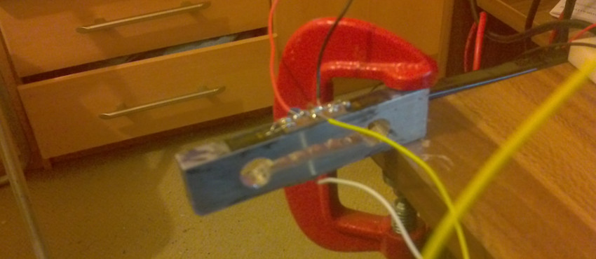
So now I have aluminium beam, next task is to glue strain gauge on it or in some other ways attach it to the aluminium bar.
One of the trickiest parts is to actually stick the strain gauge on the beam. The kit costs around 120$, which includes degreaser, M-BOND 200 adhesive, catalyst C and other tools for properly handling the strain gauge. First of all, the instrument should be used with gloves, it can be easily damaged and the resistance can change if your fingers come in contact with the strain gauge. Hopefully, for our project we won’t need to buy the super expensive kit, we might need to borrow degreaser from somewhere, only if our beam is dirty. M-BOND 200 adhesive is essentially super glue, which can last longer than common super glue, after quick research I found out, that it is possible to use typical super glue for applying strain gauge to the beam, however it is not recommended, because the duration of the device might be only a little bit over a year. Since we are delivering a prototype, we can use normal super glue for sticking the sensor to the aluminum beam. And the catalyst C is used for increasing the measurements precision, we won’t need it, because we have a huge error margin 5g to be exact, normal catalyst C is used if you want to do very precise measurement, for instance 0.1 g. There are some good instruction videos on the WEB from different universities, explaining exactly how to do it.
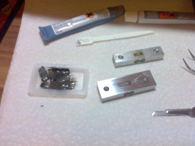
I gathered these materials to glue the strain gauge on the aluminum:
- Superglue
- Duct tape
- Sand paper
- Acetone
And I did these steps in order to apply the strain gauge on the beam:
- Sanded the surface, where I’m about to apply strain gauge
- Cleaned the surface with acetone
- With tweezers aligned the strain gauge in the middle of the beam
- With duct tape fixed the strain gauge in place
- Slowly pealed back the duct tape with strain gauge stuck to it
- Under the strain gauge applied super glue
- Glued the duct tape with strain gauge back to the surface of the beam
Problems Encountered
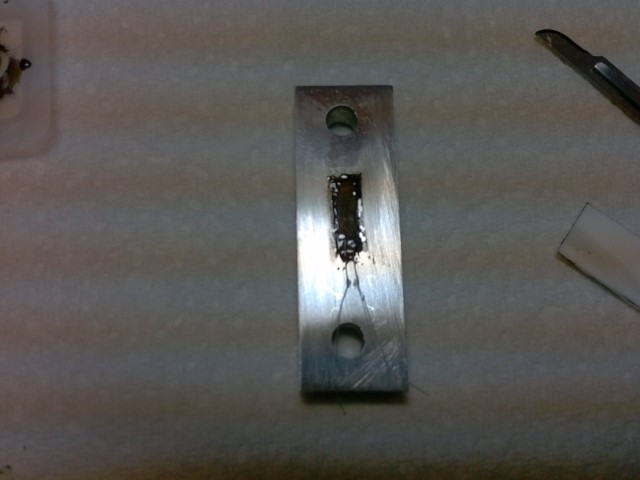
I was wrong about the superglue, it didn’t work at all. It is impossible to stick the strain gauge to aluminium with super glue. Basically the glue acted as droplet on the surface and was constantly repealing from it. So I went back to research and found out, that I had to use epoxy glue. So I redid all the above steps but instead of superglue I used epoxy, and this time it was possible to glue the strain gauge on the surface of the beam.
Results:
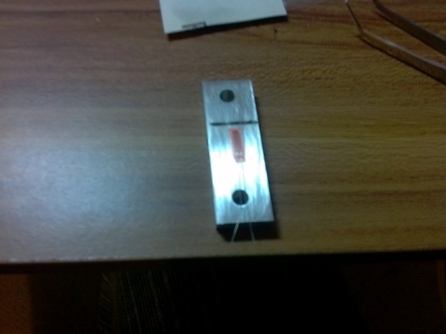
After soldering the wires with multi-meter I measured whether it produces 1kΩ of resistance, and if I bend it, does it change slightly. And I can confirm it still is working now I have to design an amplification circuit to do actual weight measurements.
Design amplification circuit
Wheatstone bridge
Because the change of resistance is very small, it’s a little bit trickier than just measuring resistance between two points, since the change in weight is measured in micro-ohms. So we have to find a way to measure these small changes. Commonly, used circuit for sensitive resistance measurements is Wheatstone bridge. This circuit is commonly used for converting the micro-strains into voltage changes, that can be then fed into ADC pin in micro-controller. Essentially, Wheatstone bridge is four resistors connected in a square. When the bridge is perfectly balanced the output voltage would be 0, but if one of the resistors slightly changes, the bridge produces significant measurable voltage. Still the Vout would be in mV. When used with a strain gauge, one of the resistors in the bridge will be replaced by the sensor and when the strain gauge undergoes dimensional changes, it will unbalance the Wheatstone bridge proportional to the strain.
In picture above you can see Quarter Wheatstone bridge, which has only one resistor replaced by the strain gauge. Typically, the resistors R1, R2, R3 are the same as unstrained resistance of strain gauge. One thing we have to remember when using strain gauge, the wire resistance plays significant role when balancing this bridge. Because, as stated above, the changes are in micro-ohms, and wire resistance can influence the results. This circuit can be used for weight sensing, but it has one significant problem, the strain gauges resistance varies in different temperatures. For our case, we might be able to compensate that in software, because our error of margin can be up to 5 g.
Amplification circuit
So we have to design amplification circuit which can amplify the voltage difference generated in Wheatstone bridge. To accomplish this task we will be using a difference op-amp amplification circuit.
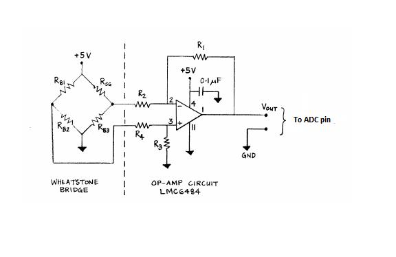
Difference amplifier with wheatstone bridge
R1 = R3 = 1MΩ
R2 = R4 = 100kΩ
The gain should be Av = R1/R2 = 10
Further Research and Planning
When we assembled the Wheatstone bridge and the difference amplification circuit, we basically didn’t get any good measurements. It is a failure. The weight sensor is generating very noisy data and sensitivity is about 100g. Probably we could get more sensitivity out of the sensor if we amplify the output more, however as I stated it is already buried in noise.
Problem evaluation
We found out that one source of noise is the 1% metal film resistors used to balance the Wheatstone bridge. It is rather amazing that those resistors are changing by 0.5Ω, which significantly misbalances Wheatstone bridge.
Probable solutions
- Cut the width of the sensor as small as possible
- Use full-bridge circuit, where all of the Wheatstone bridge resistors are strain gauges, essentially we need 4 strain gauges
Results
After we built load cell with 4 strain gauges and on a thinner load cell, the sensitivity of the sensor was essentially the same, only thing we managed to get rid of was the noise. So we could amplify it more, and we did. Unfortunately when we amplified more the noise appeared again and still the sensitivity wasn’t increased a bit. Apparently, I have made huge mistake somewhere in my load cell design.
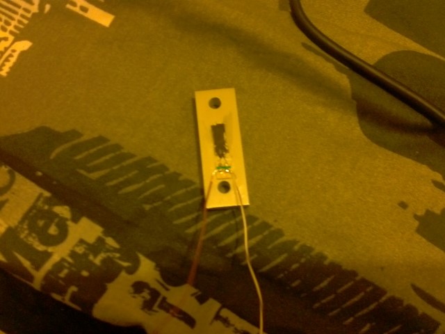
Failed weight sensor
New aluminium bar design (WORKING)
After week of frustration we found out that the design of the aluminium beam is completely incorrect. The way current beam’s design distributes strain doesn’t comply with Hooke’s law, and the 4 strain gauges are not able to amplify each other, what actually they do is they cancel each other out.
Basically, my design isn’t acting as spring element. It should have been something similar in the picture below:
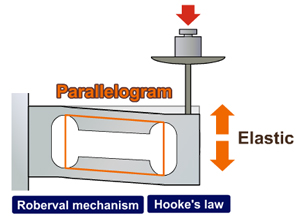
Proper load cell design
Source: http://www.ishida.com/technologies/loadcell/html.html
Back to designing
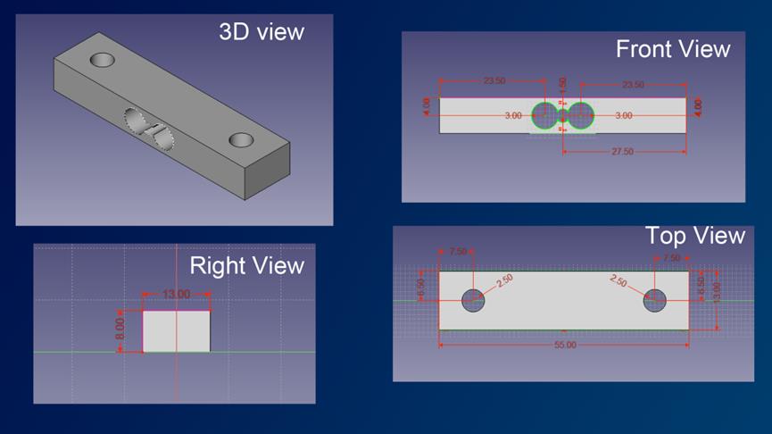
So now we theoretically know how the load cell should be constructed, I made a new blueprint for the load cell.
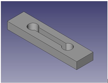
3Dview of new load cell design
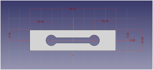
Blueprint for the new load cell
Now when we have a blueprint it’s time to make the actual aluminium beam. Fortunately for me I still had enough leftover aluminium to make it.
LET'S GET TO WORK
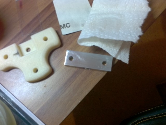
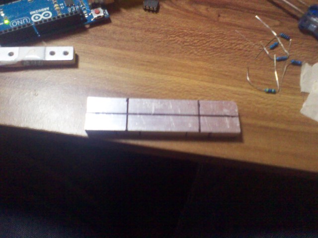 Marking the drilling holes
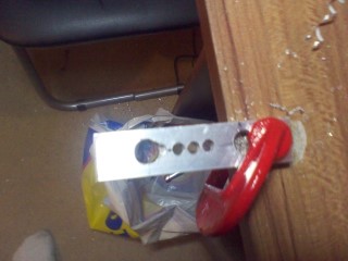
 Slightly smaller, first two holes drilled
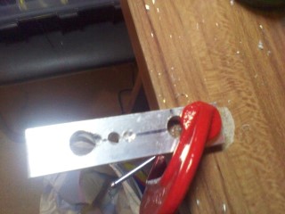
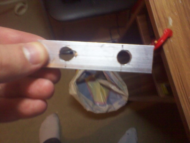 Two of the big holes drilled
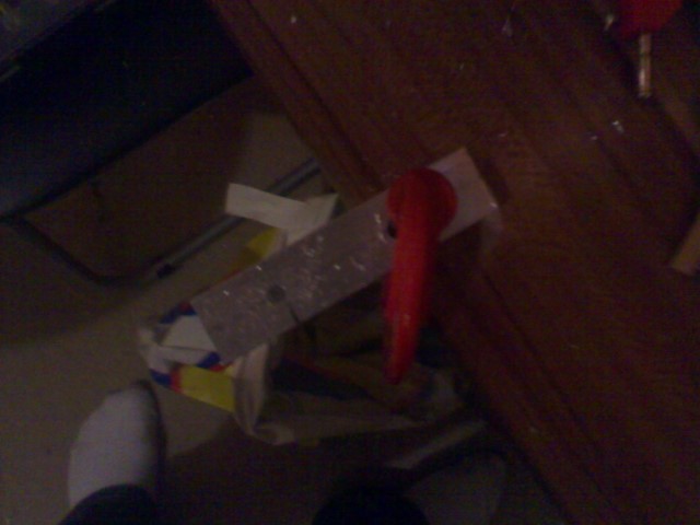
 Drilling the middle part
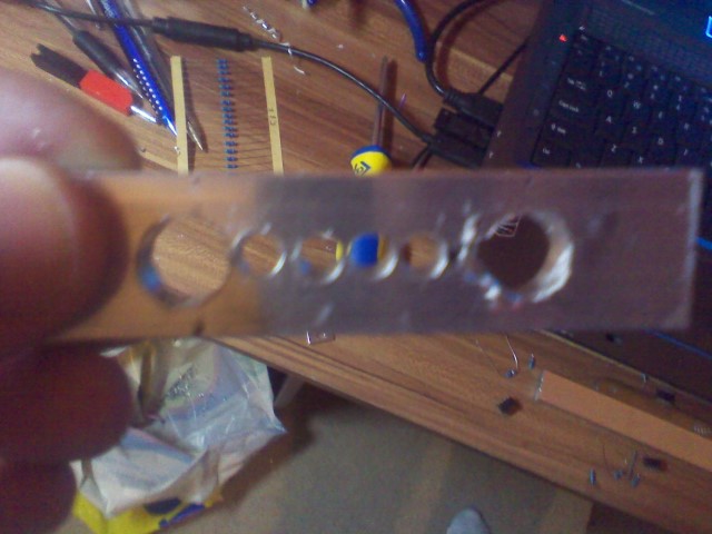 Middle has been drilled. Now it's time to merge them with a file.
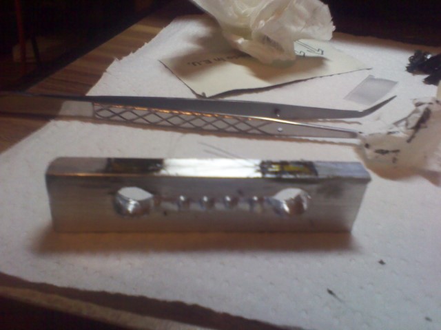 After merging the middle, started glueing strain gauges over the big holes
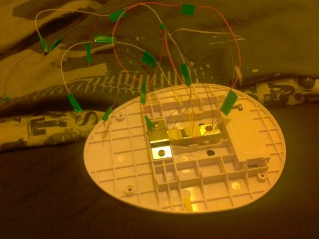
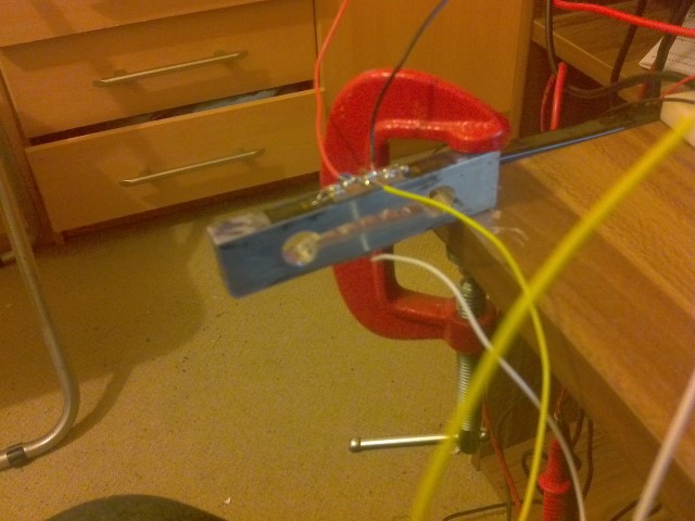 Fully assembled load cell, with wheatstone bridge soldered on the beam.
Results
After assembling load cell we tested with current amplification circuit and the difference was huge. Finally after frustrating 3 months I have a working prototype for weight sensor. However, it has a strange drift and still there is noise. If I can sort this out the sensitivity is more than enough to detect one Duplo block.
Redesigning amplification circuit
I found out that strain gauges are amplified by instrumentation amplifiers. IN-AMPS are designed for high gain amplification with low noise. I asked the technician in the Analogue lab whether they have a single unit IN-AMP, unfortunately for me they don’t. However I looked at the IN-AMP circuit diagram it doesn’t look too complicated. Basically an IN-AMP is just a 3 stage op-amp circuit.
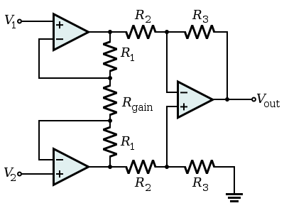 IN-AMP circuit diagram
Basically the first stage or the first two op-amps amplify the difference voltage between V1 and V2. The first stage amplification can be calculated with the following equation:
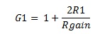
One thing to remember is that the first two amplifiers will try to preserve the amplified difference. I have to be careful not to go below saturation voltage, since I’m using LM741 op-amps it can’t go below 1.2V and over 5V limit so I wouldn’t burn the Arduino. Another thing to remember with these IN-AMPS is that they have common-mode voltage, for LM741 I guess they are 0.5V, so the difference always will be 0.5V. It can be a problem if you have operating range from 0 volts, since it will try to get negative voltage in one of the outputs.
The third and last amplifier is just a difference amplification circuit where it subtracts V+ from V-. You can do amplification at this stage as well by changing the R2 and R3 resistors.
Basically the total gain can be calculated with the following equation:
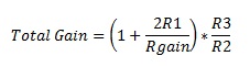
So now that I know all the theory and equation behind the IN-AMP it’s time to calculate the resistor values for it.
My 0 weight difference is 1.1 mV and for Arduino protection purpose I will assemble the voltage difference to go down when I apply the weight, so I want my 0 weight to be around 5V
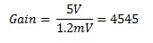
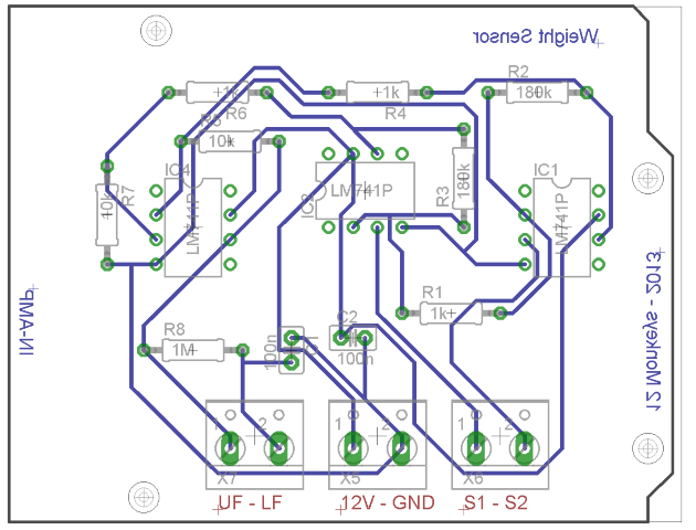
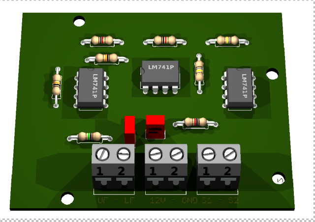
Basically I need gain of around 4000. For my amplification circuit I chose the following resistors:
R1 = 180kΩ
Rgain = 1kΩ
R2 = 1kΩ
R3 = 10kΩ
This will give me total gain of 3610. That means my 0 weight will produce around 3.9V. So I now have a 2.7V margin for around 750g.
I tested the weight of one Duplo block which produced 25mV of change I know that Duplo block is 12.4g. From that we can calculate the maximum weight you can measure and the Arduino’s resolution for measuring the weight.
So 1g will produce 2.04mV of change. That means maximum weight amplifier can handle would be: Max Weight = 2.7V / 2.04mV = 1.32kg . Which is in the range of my functional requirements, my goal was to make a sensor which can handle up to 750g. Unfortunately, Arduino’s ADC smallest measurement in range of 5V is 5mV, which means my resolution would be 2.45g, and again it is in the range of my functional requirements, since I had to design a sensor which could at least measure 12.4 g.

IN-AMP prototype on breadboard
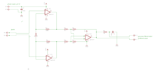 Final IN-AMP circuit diagram. At the end of the page you can download the project folder the circuit will be there.
Code for interfacing sensor with arduino
So one of the problems I have to overcome is the noise, from past experience a simple averaging should do the trick of filtering most of the noise out. In addition I have to make a tear function which will reset the weight measurements to 0.
Since my speciality is actually programming very quickly I wrote these two functions for arduino:
getWeight() function:
int getWeight()
{
  int totalValue = 0;
  for(unsigned char i = 0; i<AVG_COUNT; i++)
  {
    totalValue += analogRead(A0);
    delay(1);        // delay in between reads for stability
  }

  totalValue = (totalValue / AVG_COUNT) - tearValue;

  return -totalValue;
}

resetTear() function
void resetTear()
{
  int total = 0;
  for(unsigned char i = 0; i<AVG_COUNT; i++)
  {
    total += analogRead(A0);
    delay(10);        // delay in between reads for stability
  }
  total /= AVG_COUNT;
  tearValue = total;
}
Results
Well it did slightly work, but I’m not very satisfied with the results, I think even simple averaging is not enough for smoothing out noise, as you can see in the graph below:
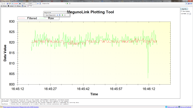 Output from arduino with average value filtering
Improving the filter
After quick search I found a very easy to implement and actually very common filter called moving average. Essentially what it does it uses previous results for smoothening the next ones.
int getWeight()
{
  int totalValue = 0;
  for(unsigned char i = 0; i<AVG_COUNT; i++)
  {
    totalValue += analogRead(A0);
    delay(1);        // delay in between reads for stability
  }

  totalValue = (totalValue / AVG_COUNT) - tearValue;

  long total = 0;
  for(unsigned char i=0; i<29; i++)
  {
    movingAvg[i] = movingAvg[i+1];
    total += movingAvg[i];
  }
  movingAvg[29] = totalValue;
  total += totalValue;
  total /= 30;

  return -total;
}
More or less the code is the same, I still do simple averaging for calculating current result, but I have added an array where I save all the previous results and after taking the current one I calculate the average between them, hence it’s called moving average.
The results are overwhelming:
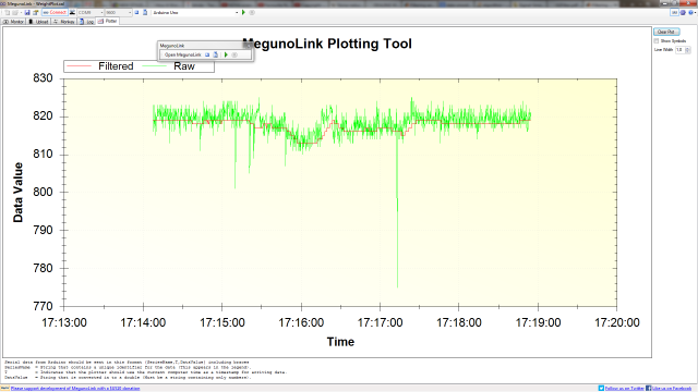 Moving averaging filter
Electromagnetic interference problem
For a little while I was happy that the weight sensor is basically done, until I encountered strange noise which couldn’t be filtered. And I couldn’t find the source of it, I thought by bringing the sensor to university somehow I bent the wires I broke it. However by accident we found out that the noise was actually electromagnetic interference. Basically while I was looking for the source of the noise, one of my group colleges was talking through a mobile phone, as soon as he finished the sensor stabilized and there was basically no noise what so ever. Of course we tested it again. We put one of the mobile phones near the weight sensor and called it, just like predicted we got huge noise detected by Arduino. Even 2m away with an active phone call has significant interference.
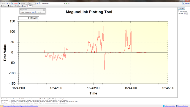
Electromagnetic interference
Basically those huge spikes are mobile phone conversations
Probable Solutions
- Decrease the size of the load cell beam, and get better strain gauges, so you don’t have to have a gain of 4000.
- Decreasing the length of wires, coming to IN-AMP
- Wrapping wires in an aluminium foil and connecting it to AGND
- Wrapping the case with aluminium foil
- Soldering everything in PCB
Testing Phase
Standalone Testing
I did small testing whether one Duplo block can be detected, and whether it will be linear with different amount of blocks placed on the sensor. First we just tested one Duplo block as you can see in the graph below:
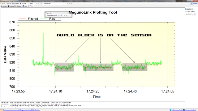 Measuring one duplo block
Table of measurements:
|
Actual weight (g) |
Weight measured by sensor (g) |
Error % |
|
12.4 |
12 |
3.22% |
|
36 |
34.72 |
3.68% |
|
120 |
119.04 |
0.8% |
|
240 |
238.08 |
0.8% |
|
496 |
498.48 |
0.5% |
Conclusion
The sensor seem to be more or less linear, even the error percentage drops when you go on higher weights, which might be caused by the fact that I’m using integers to store my values. Basically when I get a result 12.6 the integer will hold 12, but for larger values if I get these kind of integer related errors they cancel out in error percentage because of the insignificance when it comes to small fractions of error produced by integer data type. It can be fixed by properly flooring the weight results, or using double data type.
References
Texas Instrument [No Date] LMC6484 CMOS Quad Rail-to-Rail Input and Output Operational Amplifier [Online] Available at http://www.ti.com/lit/ds/symlink/lmc6484.pdf (Accessed on 10.10.2012)
All About Circuits[No Date] Strain gauges [Online] Available at http://www.allaboutcircuits.com/vol_1/chpt_9/7.html (Accessed on 10.10.2012)
Bitesize[No Date] Differential Amplifier [Online] Available at http://www.bbc.co.uk/bitesize/higher/physics/elect/analogue/revision/3/ (Accessed on 15.10.2012)
Analog[No Date] AD620: Low Drift, Low Power Instrumentation Amp with Set Gains of 1 to 10000 [Online] Available at http://www.analog.com/en/specialty-amplifiers/instrumentation-amplifiers/ad620/products/product.html (Accessed on 18.10.2012)
FSR[No Date] Force Sensing Resistors An Overview of the Technology [Online] Available at http://www.sparkfun.com/datasheets/Sensors/Pressure/fsrguide.pdf (Accessed on 19.10.2012)
Spectrasymbol[No Date] Membrane Potentiometer [Online] Available at http://www.sparkfun.com/datasheets/Sensors/Flex/SoftPot-Datasheet.pdf (Accessed on 19.10.2012)
Sharif[No Date] Mechanical Properties [Online] Available at http://mehr.sharif.ir/~amirkhani/textbook/chap07.pdf (Accessed on 23.11.2012)
degussa[No Date] PLEXIGLAS XT[Online] Available at http://www.rhinepolymers.com/plexiglas_brochures/PLEXIGLAS-XT-Basic-grades.pdf (Accessed on 23.11.2012)
Omega[No Date] Introduction to Strain Gages [Online] Available at http://www.omega.com/prodinfo/StrainGages.html (Accessed on 05.01.2013)
University of California [No Date] Strain Gage Sensors [Online] Available at http://www.ni.com/pdf/academic/us/me104_lab3_2003.pdf (Accessed on 05.01.2013)
Nakka Rocketry [June 2002] MOUNTING STRAIN GAGES TO THE LOAD CELL BODY [Online] Available at http://www.nakka-rocketry.net/articles/Gages.PDF (Accessed on 16.01.2013)
Ishida[No Date] Load Cell[Online] Available at http://www.ishida.com/technologies/loadcell/html.html (Accessed on 15.02.2013)
Gas station without pumps [30.06.2012] Instrumentation Amp Lab[Online] Available at http://gasstationwithoutpumps.wordpress.com/2012/06/30/instrumentation-amp-lab/ (Accessed on 23.02.2013)