Recently I’ve been playing with cheap GY-80 module, more precisely 10DOF module with accelerometer, gyroscope, magnetometer and barometer. Eventually I’ll write how to use all four of them. I’ll start with accelerometer (accel). This guide could potentially be used for interfacing most of the MEMS accels, and definitely as a guide how to interpret data coming from the accel, not only from MEMS but also how to use the data coming from Smartphone, wiimote etc. They are basically the same thing. However, I won’t be describing features as tap sensing and double tap sensing, this will be only an introduction about the raw accelerometer.
What is accelerometer anyway?
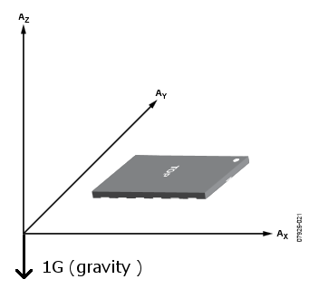
Short answer, a device that measures the acceleration in a specific direction from gravity and movement. In our case ADXL345 is a 3 axis accel, basically it can measure acceleration in 3 directions simultaneously. On Earth, accelerometer when placed on a flat surface will always measure 9.81m/s2.In most cases you’ll find that acceleration is measured in g-forces, which is basically acceleration felt as weight. Obviously at Earth surface and in restful condition we experience 1G.
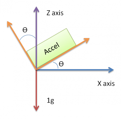
In most cases the acceleration is used as a vector quantity, which can be used to sense the orientation of the device, more precisely pitch and roll. Because when you turn the device, the 1G component is distributed among those 3 axes. With simple vector math we can calculate the angle of the device.
Initializing ADXL345
In this tutorial, I’ll be using I2C protocol for communicating with the ADXL345. The basic principle of communication with device is as following. First, you send the address of register you either want to read or write. Then you send the new values to write in the corresponding register or request specific amount of bytes from the device.
The initialization of ADXL345, consists of three things, enabling measurement mode in register POWER_CTL, specifying the data format and setting the offset in registers – OFSX, OFSY, OFSZ.
To start the measurements we just need to set bit 3 in POWER_CTL register, basically we just write 0x08 to it, like so:
writeTo(ADXL345_POWER_CTL, 0x08);
After we have successfully started our ADXL345, we can now specify the data format in other words, the resolution of the measurements. See table below for the register DATA_FORMAT
In our case, we are just interested in 3 bits - D3, D1 and D0. When FULL_RES bit is enabled, the device will run in full resolution mode, in other words, it will always maintain 4mG/LSB. No matter what range is specified, one bit will represent 4mG of acceleration. If it is not enabled the ADXL345 will run in 10-bit mode, and the range bits will determine how many mg/LSB.
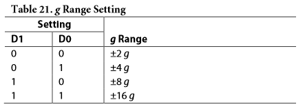
The Range bits basically sets the range of the measurements, see table below for possible configurations:
See table below for mG/LSB in different range configurations:
In my case I’ve decided I’ll be using ±16 g range in full resolution, according to my preferences and the table I’ve provided above, I’ve to send 0x0B to the register DATA_FORMAT
writeTo(ADXL345_DATA_FORMAT, 0x0B);
The final step is optional; you can easily have a working accel, without specifying the offset. To compensate for the offset, I’m using the built in registers in the ADXL345 and I’ve added ability to do the same in software as well.
As I mentioned previously, the offset is specified in registers – OFSX, OFSY and OFSZ. The offsets are stored in two compliments format and are automatically added to the output register. However, there is a downside using hardware offset, it is limited to how precise you can specify the offset, due to scale factor of 15.6 mG/LSB. Because of this limitation in the library I added software offset as well, so I can specify the offset in less than 15.6 mG as well. The offset is calculated for each accelerometer separately, don’t use my measurements, you’ll just make your accel to be even less precise.
The full code for initializing:
void ADXL345::init(char x_offset, char y_offset, char z_offset)
{
  writeTo(ADXL345_POWER_CTL, 8);

  writeTo(ADXL345_DATA_FORMAT, 0x0B);

  writeTo(ADXL345_OFSX, x_offset);
  writeTo(ADXL345_OFSY, y_offset);
  writeTo(ADXL345_OFSZ, z_offset);
}
Reading the raw acceleration and converting to Gs
At this point we are ready to read the data from the accelerometer. The accelerations in raw format are stored in registers – DATAX0, DATAX1, DATAY0, DATAY1, DATAZ0 and DATAZ1.
The results are divided in two 8 bit registers forming 16 bit registers where the format is LSB is first then followed by MSB. Again the data are stored in two’s compliment format. With I2C protocol, it is possible to request multiple bytes in one reading session. So to read the data, you can just provide the address of DATAX0 and request 6 bytes. It is also recommended by the datasheet to prevent a change in data between reads of sequential registers.
After we have read raw data from the acceleration, we need to convert them to Gs. Basically, we just how to multiply the raw data with a pre-calculated constant, which changes according to your “Range” and “full resolution” settings.
In my case, I’m using 16 bit mode and full resolution, which gives me around 3.9mG/LSB. So that means I’ve to multiply the data with 0.0039 to convert the raw data to Gs. See the table above for constants according to your settings.
See the code below on how I’m reading and converting the accelerometer raw data to Gs:
AccelG ADXL345::readAccelG()
{
  AccelRaw raw;
  raw = readAccel();


  double fXg, fYg, fZg;
  fXg =raw.x * 0.00390625 + _xoffset;
  fYg =raw.y * 0.00390625 + _yoffset;
  fZg =raw.z * 0.00390625 + _zoffset;

  AccelG res;

  res.x = fXg * ALPHA + (xg * (1.0-ALPHA));
  xg = res.x;

  res.y = fYg * ALPHA + (yg * (1.0-ALPHA));
  yg = res.y;

  res.z = fZg * ALPHA + (zg * (1.0-ALPHA));
  zg = res.z;

  return res;


}

AccelRaw ADXL345::readAccel()
{
  readFrom(ADXL345_DATAX0, ADXL345_TO_READ, _buff); //read the acceleration data from the ADXL345

  // each axis reading comes in 16 bit resolution, ie 2 bytes. Least Significat Byte first!!
  // thus we are converting both bytes in to one int
  AccelRaw raw;
  raw.x = (((int)_buff[1]) << 8) | _buff[0];
  raw.y = (((int)_buff[3]) << 8) | _buff[2];
  raw.z = (((int)_buff[5]) << 8) | _buff[4];

  return raw;
}
Not that in my readAccelG function I’ve also implemented a simple low pass filter:
res.x = fXg * ALPHA + (xg * (1.0-ALPHA));
Basically, I just take the component of the current accelerometer data and the previous one and sum them up to produce the new acceleration. The ALPHA can be anything between 0 and 1. The lower the ALPHA the lower frequencies will be filtered.
Calculating pitch and roll
One of the most common uses of accelerometer is to measure tilt on a particular axis. Remember, previously I mentioned that accelerometer on a flat surface would produce 1g on one of its axis (most likely Z). The output of accelerometer is not linear but rather a sine wave, so you can’t just convert g-forces proportionately to tilt in degrees.
Measuring tilt with one axis
The simplest way to measure the tilt, is to use only one axis. Basically the inverse of sine function will give you the angle.
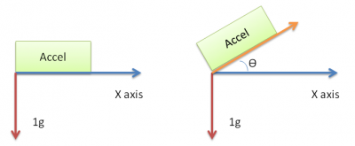
So Ɵ = sin-1 (x). However due to nature of sine wave you can measure the tilt reliably from 45° to -45°. Past those points the sensitivity of measurements are significantly reduced.
Measuring tilt with two axis
A slightly more reliable method for calculating tilt, is to use two axis. Then you can measure from 90° to -90°, without any loss to sensitivity. Remember high school geometry:
Using two axes significantly improves the accuracy of measuring the angle. However, if your accelerometer is slightly turned in direction of Y axis, your measurements will again be imprecise, since some of the component of the vector from Z axis will be “lost” to Y axis.
Measuring tilt with three axis
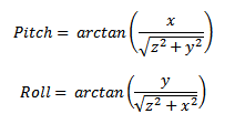
To have the best accuracy when measuring tilt, you must use all three axes to determine the angle. Basically the same arctan equation is used, but instead of simply dividing by one axis, we calculate the magnitude between other two axes.
With the equation above we would calculate the angle between the gravity vector and X axis. Depending how you accelerometer is placed on the board; it can either be pitch or roll.
Basically, you have to determine on which axis for you is roll and on which is pitch.
In my case I calculate the pitch and roll like this:
To implement those two equations in code I used atan2 function, which provided by the math library in C and C++. The atan2 function returns the angle in radians, so again remember high school math that 1 radian = 180/π, which is around ~57°.
rot.pitch = (atan2(accel.x,sqrt(accel.y*accel.y+accel.z*accel.z)) * 180.0) / PI;
rot.roll = (atan2(accel.y,(sqrt(accel.x*accel.x+accel.z*accel.z))) * 180.0) / PI;
Calculating velocity and distance traveled (for educational purposes)
First of all, I advise not to use accelerometer to calculate neither the velocity nor distance, due to integral being only approximate in the code. Because the integral will be only approximation you’ll quickly get an error in your distance and speed. Especially in distance, since to calculate that, you have to use double integral.
First acceleration is change in speed in unit time:
From this we can derive that:
To calculate the velocity, you have to periodically take measurements from the accelerometer and multiply exactly by the time difference and add it to the current acceleration:
The more frequently you’ll take the samples, the less error you’ll have. However, because you can’t take infinite amount of measurements between two units of time, the velocity eventually will generate an error. Most likely it won’t even go back to initial state 0.
To calculate the distance, we just use the following equation:
And again, periodically you must calculate the distance traveled and add to the previously calculated distance:
The same problem applies as to calculating velocity when calculating the distance. Because you can’t have infinite measurements between, your integral will be an approximation and will generate an error. In practice because you would use double integral, the distance will generate the error VERY quickly, mainly because, the speed will never reach 0. It will always be something close to 0, and your distance will just drift in either direction. The more samples you’ll take and the more precise integral you’ll have the less drift you’ll have.
To avoid the drift in distance and velocity, you might want to consider using GPS together with the accelerometer. To fuse those sensors you can either use simple complementary filter or kalman filter. Or just don’t use the accelerometer for measuring distance or velocity
Implementing everything in code (Arduino)
Finally, all the necessary theory has been covered on how the ADXL345 accelerometer works and how to interpret and use the data provided by accelerometers. I won’t be going in detail through the code, because I believe it is self explanatory, especially due to me mentioning and giving examples of code while writing the theory.
Sample usage:
#include "ADXL345.h"

ADXL345 accel;

void setup()
{

  Serial.begin(115200);

  Serial.println("Ready.");
  Wire.begin();

  accel.init(-1, 0, 8);
  accel.setSoftwareOffset(-0.023, 0, 0.03577027);
  accel.printCalibrationValues(40);

}

void loop()
{
  //ACCEL
  AccelRotation accelRot;

  accelRot = accel.readPitchRoll();
  Serial.print("{P0|Pitch|127,255,0|");
  Serial.print(accelRot.pitch);


  Serial.print("|Roll|255,255,0|");
  Serial.print(accelRot.roll);
  Serial.println("}");


  AccelG accelG;
  accelG = accel.readAccelG();
  Serial.print("{P1|Xg|255,0,0|");
  Serial.print(accelG.x);


  Serial.print("|Yg|0,255,0|");
  Serial.print(accelG.y);

  Serial.print("|Zg|0,0,255|");
  Serial.print(accelG.z);
  Serial.println("}");
  //END ACCEL
}
ADXL345.h file
#ifndef ADXL345_h
#define ADXL345_h

#include <Wire.h>
#include "Arduino.h"


#define ADXL345_DEVICE 0x53
#define ADXL345_TO_READ 6

#define ADXL345_POWER_CTL 0x2d
#define ADXL345_DATAX0 0x32
#define ADXL345_DATA_FORMAT 0x31

#define ADXL345_OFSX 0x1E
#define ADXL345_OFSY 0x1F
#define ADXL345_OFSZ 0x20

#define ALPHA 0.5


struct AccelRaw
{
  int x;
  int y;
  int z;
};

struct AccelG
{
  double x;
  double y;
  double z;
};

struct AccelRotation
{
  double pitch;
  double roll;
};

class ADXL345
{
  public:
    ADXL345();
    void init(char x_offset=0, char y_offset=0, char z_offset=0);
    void writeTo(byte address, byte val);
    AccelRaw readAccel();
    AccelG readAccelG();
    void readFrom(byte address, int num, byte _buff[]);
    void printAllRegister();
    void print_byte(byte val);
    void printCalibrationValues(int samples);
    AccelRotation readPitchRoll();
    void setSoftwareOffset(double x, double y, double z);


  private:
     byte _buff[6];

     double xg;
     double yg;
     double zg;

     double _xoffset;
     double _yoffset;
     double _zoffset;


};

#endif
ADXL345.cpp file
#include "Arduino.h"
#include "ADXL345.h"

#include <math.h>

ADXL345::ADXL345()
{
  xg =0;
  yg=0;
  zg=0;
}

void ADXL345::init(char x_offset, char y_offset, char z_offset)
{
  writeTo(ADXL345_POWER_CTL, 8);

  writeTo(ADXL345_DATA_FORMAT, 0x0B);

  writeTo(ADXL345_OFSX, x_offset);
  writeTo(ADXL345_OFSY, y_offset);
  writeTo(ADXL345_OFSZ, z_offset);
}

void ADXL345::setSoftwareOffset(double x, double y, double z)
{
  _xoffset = x;
  _yoffset = y;
  _zoffset = z;
}

AccelRotation ADXL345::readPitchRoll()
{
  //http://developer.nokia.com/community/wiki/How_to_get_pitch_and_roll_from_accelerometer_data_on_Windows_Phone
  //http://www.hobbytronics.co.uk/accelerometer-info

  AccelG accel;
  accel = readAccelG();

  AccelRotation rot;

  rot.pitch = (atan2(accel.x,sqrt(accel.y*accel.y+accel.z*accel.z)) * 180.0) / PI;
  rot.roll = (atan2(accel.y,(sqrt(accel.x*accel.x+accel.z*accel.z))) * 180.0) / PI;

  return rot;
}


void ADXL345::printCalibrationValues(int samples)
{
  double x,y,z;
  double xt,yt,zt;
  xt = 0;
  yt = 0;
  zt = 0;

  Serial.print("Calibration in: 3");
  delay(1000);
  Serial.print(" 2");
  delay(1000);
  Serial.println(" 1");
  delay(1000);

  for(int i=0; i<samples; i++)
  {
    AccelG accel = readAccelG();
    xt += accel.x;
    yt += accel.y;
    zt += accel.z;
    delay(100);
  }

  Serial.println("Accel Offset (mg): ");
  Serial.print("X: ");
  Serial.print(xt/float(samples)*1000,5);
  Serial.print(" Y: ");
  Serial.print(yt/float(samples)*1000,5);
  Serial.print(" Z: ");
  Serial.println( zt/float(samples)*1000,5);

  delay(2000);
}


// Writes val to address register on device
void ADXL345::writeTo(byte address, byte val)
{
  Wire.beginTransmission(ADXL345_DEVICE); // start transmission to device
  Wire.write(address); // send register address
  Wire.write(val); // send value to write
  Wire.endTransmission(); // end transmission
}

AccelG ADXL345::readAccelG()
{
  AccelRaw raw;
  raw = readAccel();

  //Scale = (16*2)/2^13

  double fXg, fYg, fZg;
  fXg =raw.x * 0.00390625 + _xoffset;
  fYg =raw.y * 0.00390625 + _yoffset;
  fZg =raw.z * 0.00390625 + _zoffset;

  AccelG res;

  res.x = fXg * ALPHA + (xg * (1.0-ALPHA));
  xg = res.x;

  res.y = fYg * ALPHA + (yg * (1.0-ALPHA));
  yg = res.y;

  res.z = fZg * ALPHA + (zg * (1.0-ALPHA));
  zg = res.z;

  return res;


}

AccelRaw ADXL345::readAccel()
{
  readFrom(ADXL345_DATAX0, ADXL345_TO_READ, _buff); //read the acceleration data from the ADXL345

  // each axis reading comes in 16 bit resolution, ie 2 bytes. Least Significat Byte first!!
  // thus we are converting both bytes in to one int
  AccelRaw raw;
  raw.x = (((int)_buff[1]) << 8) | _buff[0];
  raw.y = (((int)_buff[3]) << 8) | _buff[2];
  raw.z = (((int)_buff[5]) << 8) | _buff[4];

  return raw;
}

// Reads num bytes starting from address register on device in to _buff array
void ADXL345::readFrom(byte address, int num, byte _buff[])
{
  Wire.beginTransmission(ADXL345_DEVICE); // start transmission to device
  Wire.write(address); // sends address to read from
  Wire.endTransmission(); // end transmission

  Wire.beginTransmission(ADXL345_DEVICE); // start transmission to device
  Wire.requestFrom(ADXL345_DEVICE, num); // request 6 bytes from device Registers: DATAX0, DATAX1, DATAY0, DATAY1, DATAZ0, DATAZ1

  int i = 0;
  while(Wire.available()) // device may send less than requested (abnormal)
  {
    _buff[i] = Wire.read(); // receive a byte
    i++;
  }

  Wire.endTransmission(); // end transmission
}

void ADXL345::printAllRegister()
{
    byte _b;
    Serial.print("0x00: ");
    readFrom(0x00, 1, &_b);
    print_byte(_b);
    Serial.println("");
    int i;
    for (i=29;i<=57;i++)
        {
        Serial.print("0x");
        Serial.print(i, HEX);
        Serial.print(": ");
        readFrom(i, 1, &_b);
        print_byte(_b);
        Serial.println("");
    }
}

void ADXL345::print_byte(byte val)
{
    int i;
    Serial.print("B");
    for(i=7; i>=0; i--){
        Serial.print(val >> i & 1, BIN);
    }
}
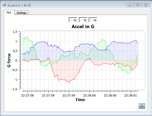
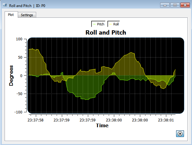
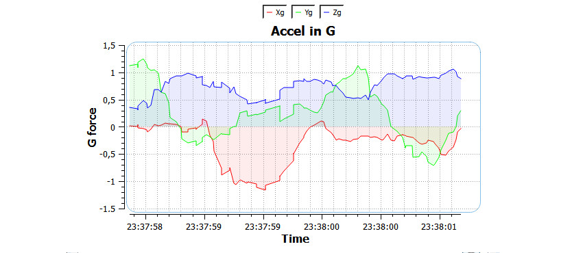
Here you can see some graphs regarding the accelerometer data:
And that's it. In part 2, I'll be describing how to use gyroscope and how to use complimentary filter to fuse accel data with gyro data. Part 2 coming soon.
References
HobbyTronics. (NA). Accelerometers. Available: http://www.hobbytronics.co.uk/accelerometer-info. Last accessed 31/05/2014.
Analog Devices. (NA). Digital Accelerometer ADXL345. Available: http://www.forkrobotics.com/wp-content/uploads/2013/05/ADXL345.pdf. Last accessed 31/05/2014.
bildr. (2011). Tap, Tap, Drop. ADXL345 Accelerometer + Arduino . Available: http://bildr.org/2011/03/adxl345-arduino/. Last accessed 31/05/2014.

