Now that we have set up the programming environment the next thing I personally like to implement on any microcontroller is a simple UART communication. Since it is really simple to do using nRF51 SDK, I thought of explaining how to implement USART and FreeRTOS in C++. Even though C is a very capable language on its own I feel restricted without OOP, I know some people might disagree but personally OOP enables me to structure my code better and is easier to pick it up after couple months of idle time. Nonetheless, this article won’t cover FreeRTOS in details; it is expected from you to know more or less what is an RTOS and what is it capable of. Also I prefer not to use printf/scanf whenever I can in embedded projects due to its large memory footprint. Since we will have the luxury of C++ we will implement a similar “Serial” library to Arduino. Honestly serial library is one of the things people behind Arduino got right.
Getting C++ working on nRF51
If you are using Qt Creator for compiling your application it will be incredibly simple to get C++ working with nRF51. It can be more of a challenge if you stick with Makefile, which I won’t be covering in this article. Actually, to get C++ working all you have to do is rename “main.c” to “main.cpp” and enclose all nRF51 sdk libraries in
extern "C" {
    #include "nrf_gpio.h"
    #include "boards.h"

    #include "timers.h"
    #include "boards.h"
    #include "bsp.h"
    #include "nordic_common.h"
    #include "nrf_gpio.h"
    #include "nrf_drv_clock.h"
    #include "sdk_errors.h"
    #include "app_error.h"
    #include "app_uart.h"

    #include "config/config.h"
}
That will tell your compiler not to screw up with the naming of the functions in the file and compile them in a fashion were C and C++ both can access the functions, but you lose overload abilities, since it is not supported by C. There are many great articles explaining how to tie C and C++ code together, I’ve referenced one of them at the end of article. It’s important to enclose all includes and functions which will be used by both languages in this “extern”.
Nonetheless, if you did what I just described to the blinky example I provided in previous article you should be able to compile it in C++. But in case you were not able to do so this is how it looks for me:
#include <stdbool.h>
#include <stdint.h>
extern "C" {
    #include "nrf_delay.h"
    #include "nrf_gpio.h"
    #include "boards.h"
}

const uint8_t leds_list[LEDS_NUMBER] = LEDS_LIST;

int main(void)
{
    // Configure LED-pins as outputs.
    LEDS_CONFIGURE(LEDS_MASK);

    // Toggle LEDs.
    while (true)
    {
        for (int i = 0; i < LEDS_NUMBER; i++)
        {
            LEDS_INVERT(1 << leds_list[i]);
            nrf_delay_ms(500);
        }
    }
}
And that’s it; you have C++ working on nRF51. Remember that if you want to call a C++ function from C you’ll also need to add in front “extern” similar to this:
extern “C” void my_function(void)
{
    //some code
}
And your C++ header file should define the function in the following way:
#ifdef __cplusplus
extern "C" {
#endif
    void function (void);
#ifdef __cplusplus
}
#endif
And then you can just call the function from your C file. This is just a quick reference on how to do it in case you need it. Once again, if you want to know more it’s worth reading Oracles guide on how to link these two languages together.
Implementing USART Serial Class
As I briefly mentioned in the introduction, I really dislike printf and scanf due to large memory footprint, so what I’ve done is I’ve taken Arduino’s “Print” class and used it to implement it in nRF51; you can probably do the same in any other ARM Cortex microcontroller with ease.
Before we continue I must warn that I wasn’t able to figure out a way to read how many bytes are in FIFO buffer without modifying the nRF51 SDK. I had two options at the time I was writing the “Serial” class either use existing FIFO and modify SDK or implement an additional FIFO on my own and leave the SDK unchanged. I chose to just do a quick modification, I think it is simpler and will have smaller RAM usage. In addition, you’ll see later that once you start using C++ it is inevitable to do some modifications in the SDK for those languages to play along.
Serial class implementation
The “Print” class requires our class to provide an overload method for the virtual size_t write(uint8_t) . And we obviously inherit all the print and println methods with their overloads. Also we need to implement the read and isAvailable methods. I thought it wouldn’t hurt to have a method for clearing the FIFO buffer, in case a task needs to clear it. We can simply call it flush.
Also note, if you look in the example code for UART provided by Nordic, you’ll see they have a function for handling an event. It is not mandatory to implement it as far as I know, but in case you need fully asynchronous way of reading the data coming from USART, I’ll show how to implement it in C++.
Taking all our requirements into account, this is how our Header file serial.h should look like:
/*
 *
Copyright (c) 2015 Raivis Strogonovs (https://morf.lv)

Permission is hereby granted, free of charge, to any person obtaining a copy of this software and associated documentation files (the "Software"),
to deal in the Software without restriction, including without limitation the rights to use, copy, modify, merge, publish, distribute, sublicense,
and/or sell copies of the Software, and to permit persons to whom the Software is furnished to do so, subject to the following conditions:

The above copyright notice and this permission notice shall be included in all copies or substantial portions of the Software.

THE SOFTWARE IS PROVIDED "AS IS", WITHOUT WARRANTY OF ANY KIND, EXPRESS OR IMPLIED, INCLUDING BUT NOT LIMITED TO THE WARRANTIES
OF MERCHANTABILITY, FITNESS FOR A PARTICULAR PURPOSE AND NONINFRINGEMENT. IN NO EVENT SHALL THE AUTHORS OR COPYRIGHT
HOLDERS BE LIABLE FOR ANY CLAIM, DAMAGES OR OTHER LIABILITY, WHETHER IN AN ACTION OF CONTRACT, TORT OR OTHERWISE, ARISING FROM,
OUT OF OR IN CONNECTION WITH THE SOFTWARE OR THE USE OR OTHER DEALINGS IN THE SOFTWARE.

*/
#ifndef SERIAL_H
#define SERIAL_H

#include "Print.h"

extern "C" {
    #include "app_uart.h"
}

/**
 * IMPORTANT
 *
 * Again modified one of the SDKs libraries
 * in app_uart_fifo.c, I added a function to be able to read how many elements are in the buffer
 *
 * static uint32_t get_fifo_byte_count()
 * {
 *    return FIFO_LENGTH(m_rx_fifo);
 * }
 *
 */

class Serial : public Print
{
public:
    Serial();
    uint32_t begin(uint8_t RX_pin, uint8_t TX_pin, uint32_t baud_rate, bool parity);

    virtual size_t write(uint8_t);
    uint8_t read();
    uint16_t isAvailable(); //Returns bytes in FIFO buffer

    void flush(); //Cleans FIFO buffer

private:
    friend void uart_event_handle(app_uart_evt_t * p_event);

};

extern Serial serial;

#endif // SERIAL_H
Ignore at the moment my comment about changing SDK, I’ll get to that in a moment.
However, until now I’ve never used friend in my code. If you are like me then this line should be interesting to you:
friend void uart_event_handle(app_uart_evt_t * p_event);
Basically for those who don’t know it allows another class to access this private method. In our case we will use it so the nRF SDK C code is able to call it as an event handle.
Also notice that we have defined an instance of this object after the Class declaration:
extern Serial serial;
We do this so we can have single instance shared between all other classes who include our serial.h file, just like in Arduino.
There is not much I can expand on the code in serial.cpp because it is really simple and just follows the sample code. Nonetheless, you should notice two things I’m not using any RTS, CTS and flow control. And on final note, if you want to asynchronously react to an event when new data is available, see the uart_event_handle() and look for these lines, which are called when data is ready:
case APP_UART_DATA_READY:
            //If you want you can make it so this here notifies some tasks directly...
            //Maybe a semiphore or queue
            break;
Here is the full code for serial.cpp
/*
 *
Copyright (c) 2015 Raivis Strogonovs (https://morf.lv)

Permission is hereby granted, free of charge, to any person obtaining a copy of this software and associated documentation files (the "Software"),
to deal in the Software without restriction, including without limitation the rights to use, copy, modify, merge, publish, distribute, sublicense,
and/or sell copies of the Software, and to permit persons to whom the Software is furnished to do so, subject to the following conditions:

The above copyright notice and this permission notice shall be included in all copies or substantial portions of the Software.

THE SOFTWARE IS PROVIDED "AS IS", WITHOUT WARRANTY OF ANY KIND, EXPRESS OR IMPLIED, INCLUDING BUT NOT LIMITED TO THE WARRANTIES
OF MERCHANTABILITY, FITNESS FOR A PARTICULAR PURPOSE AND NONINFRINGEMENT. IN NO EVENT SHALL THE AUTHORS OR COPYRIGHT
HOLDERS BE LIABLE FOR ANY CLAIM, DAMAGES OR OTHER LIABILITY, WHETHER IN AN ACTION OF CONTRACT, TORT OR OTHERWISE, ARISING FROM,
OUT OF OR IN CONNECTION WITH THE SOFTWARE OR THE USE OR OTHER DEALINGS IN THE SOFTWARE.

*/

#include "serial.h"

extern "C" {
    #include "app_error.h"
    #include "config/config.h"
}

/**@brief   Function for handling app_uart events.
 */
/**@snippet [Handling the data received over UART] */
void uart_event_handle(app_uart_evt_t * p_event)
{
    switch (p_event->evt_type)
    {
        case APP_UART_DATA_READY:
            //If you want you can make it so this here notifies some tasks directly...
            //Maybe a semiphore or queue
            break;

        case APP_UART_COMMUNICATION_ERROR:
            APP_ERROR_HANDLER(p_event->data.error_communication);
            break;

        case APP_UART_FIFO_ERROR:
            APP_ERROR_HANDLER(p_event->data.error_code);
            break;

        default:
            break;
    }
}

Serial::Serial()
{

}

uint32_t Serial::begin(uint8_t RX_pin, uint8_t TX_pin, uint32_t baud_rate, bool parity)
{
    uint32_t err_code;

    const app_uart_comm_params_t comm_params =
    {
        RX_pin,
        TX_pin,
        0, /* RTS_PIN_NUMBER */
        0, /* CTS_PIN_NUMBER */
        APP_UART_FLOW_CONTROL_DISABLED,
        parity,
        baud_rate
    };

    APP_UART_FIFO_INIT( &comm_params,
                       UART_RX_BUF_SIZE,
                       UART_TX_BUF_SIZE,
                       uart_event_handle,
                       APP_IRQ_PRIORITY_LOW,
                       err_code);
    APP_ERROR_CHECK(err_code);
}

size_t Serial::write(uint8_t data)
{
    while(app_uart_put(data) != NRF_SUCCESS);

    return 1;
}

uint8_t Serial::read()
{
    uint8_t r;

    if(isAvailable())
    {
        app_uart_get( &r );

    }

    return r;
}

uint16_t Serial::isAvailable()
{
    return get_fifo_byte_count();
}

void Serial::flush()
{
    app_uart_flush();
}

Serial serial = Serial();
Modifying the SDK
As I mentioned above I didn’t manage to find a way to get how many bytes are in FIFO in SDK 10.x.x. So I just added a new function to the SDK get_fifo_byte_count which we are using in the isAvailable method.
Basically you have to edit two files in your SDK. Or you can just download the modified files at the end of the article.
First edit “app_uart.h” file which is located in “your sdk path/components/libraries/uart”
Just add the following line at the end of the file before #endif :
uint32_t get_fifo_byte_count();
Then in the same directory edit “app_uart_fifo.c” file. And add the following function to it:
uint32_t get_fifo_byte_count()
{
    return FIFO_LENGTH(m_rx_fifo);
}
That’s all we have to do, to get how many bytes are currently in the buffer. Maybe there is already a way, but I just didn’t notice it in the code or the documentation. If there is, feel free to leave a comment and I’ll happily update the code.
Using the Serial class
It’s pretty straight forward on how to use the serial class. Remember we already have a global serial object created for use in throughout the code. Only thing we have to do is to initialize it by calling the begin method. Which is slightly different than what pure arduino has, due to the flexibility of ARM micros overall. Nearly all pins can be designated for Serial communication. The code is self-explanatory:
serial.begin(     RX_PIN_NUMBER,
                     TX_PIN_NUMBER,
                     UART_BAUDRATE_BAUDRATE_Baud38400,
                     false /* parity bit */
                 );
As you can see in addition to just providing BAUDRATE as in arduino, which is by the way defined in the “app_uart.h” file, we also specify the RX/TX pins and bit parity. In my opinion the flexibility of GPIOs in ARM Cortex micros are excellent feature which allows making the PCB much more cleanly compared to AVR architecture where you have designated pins.
And once you have initialized you use it as in Arduino, for example:
serial.println("Hello World");
if(serial.isAvailable())
{
    serial.print( serial.read() );
}
And that’s how we can implement a more efficient library for USART communication. By the way, you can also use printf in junction with this class, by just including stdio.h anywhere in your code.
FreeRTOS and C++
So what is FreeRTOS? Basically, it is a real time operating system; I like to call it “thread manager”. But my terminology might not be correct. It is not really an OS as in terms of Linux or Windows, you don’t install it, merely you have libraries which provides you with functionality to run independent tasks “simultaneously“ and do synchronization between them. If you don’t know all of this already, it might be worth reading some tutorials on what is RTOS and tutorials about FreeRTOS. It can get quite complex once you need to do something like rate-monotonic scheduling. However, for very basic tasks you don’t need to be bothered by these fancy terms. But you should know what is a semaphore, queue and how to use them to synchronize tasks. I’ve added in references great tutorial on FreeRTOS.
Well if you are familiar with FreeRTOS you’ll know it is implemented in C, and it is not that straight forward to get C++ to work. But don’t worry socialledge.com has provided a very neat and easy to use class to have C++ working with FreeRTOS. I did make some small modifications so it works on nRF51 and that instead of using “puts” it will use our “serial” class. Also I deleted some of the methods which I know I won’t be using in my project and finally the modified version won’t be able to return you utilization of each task (at least at the moment). Feel free to modify the original to your requirements or the one I’ve already modified. But be warned that the original won’t work off the bat, it does require tiny modifications to be able to compile with the newest FreeRTOS and GCC ARM compiler.
I’ll be assuming that you are using the modified version of the C++ TaskBase class when explaining how it’s used and how to implement two sample Task classes. I won’t cover queues or semaphores: see this tutorial here
Blinking LED Task
Well the most basic task we can create to test out the FreeRTOS and C++ is a simple blinking LED. Once you use C++ it is expected that all tasks will be C++, you can still use in junction with C, but the TaskBase class won’t be able to track it. Also you will require doing some small modifications to the way the scheduler is started. It won’t start if at least a single C++ task is added to the scheduler.
So let’s just get on with creating a basic Blinker task. Our task will take 5 arguments when created:
- Led number
- Blinking interval
- Task name
- Stack Size
- Priority
Note that only first two are unique to the blinker task, and arguments 3-5 will be always required for the TaskBase constructor. Once we have inherited the TaskBase, it allows us to implement three methods:
- bool init()
Which will be the very first method called only once, when the tasks are being initialized. - bool taskEntry()
This method will be called only once after all tasks have been initialized and created. In other words, post initialization method - bool run(void *param)
This method will be called continuously, until something fails or you return false. For proper usage count, return true when you are finished with the loop
Note that all of the methods mentioned above require that you return true, otherwise the library will assume that something failed in your Task and in case of the first two methods returning false will not allow running the scheduler. If you return false in run() it will just end the task. Also important, run() needs to be always implemented, init() and taskEntry() are optional.
In our blinker task, we will need only init() and run() method. Obviously in init() we will configure the provided pin as an output and in run() we will just toggle the pin and then release the task for the interval we specified as one of the arguments. Sounds simple doesn’t it? And it is!
All in all, simple led blinking task class should look something like this:
LedBlinkerTask.h file
/*
 *
 *    Copyright (c) 2015 Raivis Strogonovs (https://morf.lv)
 *
 *    Permission is hereby granted, free of charge, to any person obtaining a copy of this software and associated documentation files (the "Software"),
 *    to deal in the Software without restriction, including without limitation the rights to use, copy, modify, merge, publish, distribute, sublicense,
 *    and/or sell copies of the Software, and to permit persons to whom the Software is furnished to do so, subject to the following conditions:
 *
 *    The above copyright notice and this permission notice shall be included in all copies or substantial portions of the Software.
 *
 *    THE SOFTWARE IS PROVIDED "AS IS", WITHOUT WARRANTY OF ANY KIND, EXPRESS OR IMPLIED, INCLUDING BUT NOT LIMITED TO THE WARRANTIES
 *    OF MERCHANTABILITY, FITNESS FOR A PARTICULAR PURPOSE AND NONINFRINGEMENT. IN NO EVENT SHALL THE AUTHORS OR COPYRIGHT
 *    HOLDERS BE LIABLE FOR ANY CLAIM, DAMAGES OR OTHER LIABILITY, WHETHER IN AN ACTION OF CONTRACT, TORT OR OTHERWISE, ARISING FROM,
 *    OUT OF OR IN CONNECTION WITH THE SOFTWARE OR THE USE OR OTHER DEALINGS IN THE SOFTWARE.
 *
*/

#ifndef LEDBLINKERTASK_H
#define LEDBLINKERTASK_H

#include "FreeRTOS.h"
#include "wrapper/TaskBase.h"

class LedBlinkerTask : public TaskBase
{
public:
    LedBlinkerTask(uint8_t led_pin_num, uint32_t blink_interval, const char* task_name, uint32_t stack_size, uint8_t priority);
    bool init(void);
    bool run(void *param);

private:
    uint8_t led_pin_num;
    uint32_t blink_interval;
};

#endif // LEDBLINKERTASK_H
And LedBlinkerTask.cpp file:
#include "ledblinkertask.h"

extern "C" {
    #include "nrf_gpio.h"
    #include "boards.h"
}


LedBlinkerTask::LedBlinkerTask(uint8_t led_pin_num, uint32_t blink_interval, const char* task_name, uint32_t stack_size, uint8_t priority)
    : TaskBase(task_name, stack_size, priority )
{
    this->led_pin_num = led_pin_num;
    this->blink_interval = blink_interval;
}

bool LedBlinkerTask::init(void)
{
    nrf_gpio_cfg_output(led_pin_num);
    nrf_gpio_pin_set(led_pin_num);

    return true;
}

bool LedBlinkerTask::run(void *param)
{
    nrf_gpio_pin_toggle(led_pin_num);
    vTaskDelay(blink_interval); // Delay a task for a given number of ticks
    return true;
}
Very simple isn’t it? So the next thing we have to do is to modify our main.cpp file to run the task. Since this is a class we can easily create multiple instances for different pin numbers. Just for fun let’s create three tasks with blink interval twice as high as for the previous one and we should have a simple binary counter. However, since we are not doing any synchronization they might and probably will drift out of sync.
This is how the main.cpp file looks now with the C++ scheduler and three instances of blinker task:
#include "drivers/serial.h"

#include "wrapper/TaskBase.h"
#include "tasks/ledblinkertask.h"
#include "tasks/pwmtask.h"

#include <stdbool.h>
#include <stdint.h>

extern "C" {
    #include "boards.h"
    #include "timers.h"
    #include "boards.h"
    #include "bsp.h"
    #include "nordic_common.h"
    #include "nrf_drv_clock.h"
    #include "sdk_errors.h"
    #include "app_error.h"
    #include "config/config.h"
}


void start_tasks(void)
{
    scheduler_add_task( new LedBlinkerTask(BSP_LED_0, 2000, "LED0", 128, 2) );
    scheduler_add_task( new LedBlinkerTask(BSP_LED_1, 1000, "LED1", 128, 2) );
    scheduler_add_task( new LedBlinkerTask(BSP_LED_2, 500, "LED2", 128, 2) );


    scheduler_start(false); //This function will NEVER return
}

int main(void)
{

    ret_code_t err_code;

    err_code = nrf_drv_clock_init(NULL);
    APP_ERROR_CHECK(err_code);

    /* Activate deep sleep mode */
    SCB->SCR |= SCB_SCR_SLEEPDEEP_Msk;//Optional at the moment

    //Start the serial
    serial.begin(    RX_PIN_NUMBER,
                     TX_PIN_NUMBER,
                     UART_BAUDRATE_BAUDRATE_Baud38400,
                     false /* parity bit */
                 );

    serial.println("***** Device Booting *****");


    //It should never return from this function
    start_tasks();

    while (true)
    {
        // FreeRTOS should not be here...
    }

    return 0;
}


/* Used in debug mode for assertions */
void assert_nrf_callback(uint16_t line_num, const uint8_t *file_name)
{
  while(1)
  {
    /* Loop forever */
  }
}
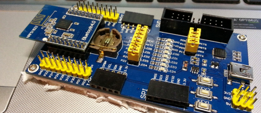
Here is a video of this code executing on the BLE400 board:
As you can see in the example code above, implementing a task in C++ and running it in FreeRTOS is really simple. Of course I haven’t covered anything regarding semaphores or queues but that is outside of the scope of this article, which already has become long.
Soft blinker/PWM task
Now that we have successfully implemented the absolutely simplest task I could imagine, we can now try to implement something a little bit more complex, but still relatively simple. And as the title of the section suggests we will implement PWM task.
You would think that implementing a PWM task would be as simple as implementing the blinky task. Unfortunately for us it is not that simple. Once again I had the pleasure to modify the SDK to play nicely with C++.
First of all, we won’t be implementing the PWM task to control directly the PWM, but we will implement a PWM driver class which will be used by our task.
At this point I have to warn you that my approach here is definitely not the best and in this case I’ve chosen flexibility over optimization/efficiency.
PWM Driver implementation
Once again you can just download the modified SDK files at the end of the article. So let’s begin by changing the SDK. Because we want to create PWM instances dynamically we need to get rid of some of the “const” statements in the nRF’s PWM library. First thing I changed it to be able to dynamically allocate the timer in app_pwm_t structure. Find the following code in “app_pwm.h” which is located “your sdk location/components/libraries/pwm/app_pwm.h”:
/**@brief PWM instance structure. */
typedef struct
{
    app_pwm_cb_t *p_cb;                    //!< Pointer to control block internals.
    nrf_drv_timer_t const * const p_timer; //!< Timer used by this PWM instance.
} app_pwm_t;
And change it to:
/**@brief PWM instance structure. */
typedef struct
{
    app_pwm_cb_t *p_cb;                    //!< Pointer to control block internals.
    nrf_drv_timer_t * p_timer; //!< Timer used by this PWM instance.
} app_pwm_t;
Another modification we have to make is to get rid of inline statement in “app_pwm.c” file, which is located in the same directory where header file is. The problem with inline statements are that they are evaluated differently on C++ and they need to be specified in header file as well and more importantly C++ is way stricter on data type than pure C.
Find this line:
inline nrf_timer_frequency_t pwm_calculate_timer_frequency(uint32_t period_us)
And just delete the inline in front of the function:
nrf_timer_frequency_t pwm_calculate_timer_frequency(uint32_t period_us)
That’s all the modifications you need to do to be able to create PWM dynamically.
Now it’s time to write the PWM driver. According to nRF SDK’s documentation every timer has two channels for PWM output, which can have different duty cycles and polarities. Excellent if you ask me, one timer can control two PWM outputs separately. Only limitation is that both channels will have the same period. In most cases shouldn’t be a problem.
So taking into account what we have learned from nRF we want 6 arguments for our PWM driver class:
- Pin number for channel 1
- Pin number for channel 2
- Polarity for channel 1
- Polarity for channel 2
- Timer id
- Period
Not always we will be using channel 2, so those will be optional and we can define a dummy value 0xFF for an unused PWM pin.
Obviously we will want to set duty cycle for each PWM; hence we need to have a method for setting duty cycle for each channel separately.
So according to our requirements and consulting the sample code for PWM provided by Nordic this is what I came up with:
PWM.h file
/*
 *
 *    Copyright (c) 2015 Raivis Strogonovs (https://morf.lv)
 *
 *    Permission is hereby granted, free of charge, to any person obtaining a copy of this software and associated documentation files (the "Software"),
 *    to deal in the Software without restriction, including without limitation the rights to use, copy, modify, merge, publish, distribute, sublicense,
 *    and/or sell copies of the Software, and to permit persons to whom the Software is furnished to do so, subject to the following conditions:
 *
 *    The above copyright notice and this permission notice shall be included in all copies or substantial portions of the Software.
 *
 *    THE SOFTWARE IS PROVIDED "AS IS", WITHOUT WARRANTY OF ANY KIND, EXPRESS OR IMPLIED, INCLUDING BUT NOT LIMITED TO THE WARRANTIES
 *    OF MERCHANTABILITY, FITNESS FOR A PARTICULAR PURPOSE AND NONINFRINGEMENT. IN NO EVENT SHALL THE AUTHORS OR COPYRIGHT
 *    HOLDERS BE LIABLE FOR ANY CLAIM, DAMAGES OR OTHER LIABILITY, WHETHER IN AN ACTION OF CONTRACT, TORT OR OTHERWISE, ARISING FROM,
 *    OUT OF OR IN CONNECTION WITH THE SOFTWARE OR THE USE OR OTHER DEALINGS IN THE SOFTWARE.
 *
*/

#ifndef PWM_H
#define PWM_H

extern "C" {
    #include "app_pwm.h"
}

#define PWM_NOPIN           0xFF

#define PWM_CH1             1
#define PWM_CH2             2

class PWMDriver
{
public:
    PWMDriver(  uint8_t pin_number_ch1,
                uint8_t pin_number_ch2,
                app_pwm_polarity_t polarity_ch1,
                app_pwm_polarity_t polarity_ch2,
                uint8_t timer_id,
                uint32_t period_in_us
           );
    bool init(void);

    bool setDuty( uint8_t ch, uint8_t duty ); //duty cycle is provided in % from 0 to 100. so a 50% duty cycle is duty = 50

private:
    uint8_t pin_number_ch1;
    uint8_t pin_number_ch2;

    uint8_t timer_id;

    app_pwm_polarity_t polarity_ch1;
    app_pwm_polarity_t polarity_ch2;
    uint8_t duty_ch1;
    uint8_t duty_ch2;

    uint32_t period_in_us;

    nrf_drv_timer_t m_pwm_timer;
    app_pwm_cb_t m_pwm_cb;
    app_pwm_t pwm;


    friend void pwm_ready_callback(uint32_t pwm_id);
};

#endif // PWM_H
And PWM.cpp file:
#include "pwm.h"

extern "C" {
    #include "nrf_gpio.h"
    #include "boards.h"
    #include "app_error.h"
    #include "app_pwm.h"
    #include "nrf_timer.h"
    #include "nrf_drv_config.h"
}


//Not mandatory, anyway I'm not using it, but you can wait for ready flag
// instead of while (app_pwm_channel_duty_set(&pwm, 0, duty) == NRF_ERROR_BUSY);
// to know when you can set new pwm duty
static volatile bool ready_flag;
void pwm_ready_callback(uint32_t pwm_id)    // PWM callback function
{
    ready_flag = true;
}


/** IMPORTANT
 *
 * Note I MODIFIED app_pwm.h app_pwm_t struct to be able to dynamically create it, instead of having 101 const
 *
 * Also in app_pwm.c I modified the following function not to be INLINE, since C99 standards are different than C++
 * inline nrf_timer_frequency_t pwm_calculate_timer_frequency(uint32_t period_us)
 *
 */


PWMDriver::PWMDriver(uint8_t pin_number_ch1,
                     uint8_t pin_number_ch2,
                     app_pwm_polarity_t polarity_ch1,
                     app_pwm_polarity_t polarity_ch2,
                     uint8_t timer_id,
                     uint32_t period_in_us
                     )
{
    this->pin_number_ch1 = pin_number_ch1;
    this->pin_number_ch2 = pin_number_ch2;

    this->polarity_ch1 = polarity_ch1;
    this->polarity_ch2 = polarity_ch2;


    this->period_in_us = period_in_us;
    this->timer_id = timer_id;


    //Another "gift" from NRF that this variable is not initialized....
    //And it will check for this flag, obviously when you're dealing with Heap this
    //can and will have some random value
    m_pwm_cb.state = NRF_DRV_STATE_UNINITIALIZED;
}

bool PWMDriver::init(void)
{
    if(timer_id == 0)
    {
#if (TIMER0_ENABLED == 1)
        m_pwm_timer.p_reg = NRF_TIMER0;
        m_pwm_timer.irq = TIMER0_IRQn,
        m_pwm_timer.instance_id = TIMER0_INSTANCE_INDEX;

        pwm.p_cb = &m_pwm_cb;
        pwm.p_timer = &m_pwm_timer;
#else
        return false;
#endif
    } else if(timer_id == 1) {
#if (TIMER1_ENABLED == 1)
        m_pwm_timer.p_reg = NRF_TIMER1;
        m_pwm_timer.irq = TIMER1_IRQn,
        m_pwm_timer.instance_id = TIMER1_INSTANCE_INDEX;

        pwm.p_cb = &m_pwm_cb;
        pwm.p_timer = &m_pwm_timer;
#else
        return false;
#endif
    } else if(timer_id == 2) {
#if (TIMER2_ENABLED == 1)
        m_pwm_timer.p_reg = NRF_TIMER2;
        m_pwm_timer.irq = TIMER2_IRQn,
        m_pwm_timer.instance_id = TIMER2_INSTANCE_INDEX;

        pwm.p_cb = &m_pwm_cb;
        pwm.p_timer = &m_pwm_timer;
#else
        return false;
#endif
    } else {
        return false;
    }

    app_pwm_config_t pwm_cfg;

    if(pin_number_ch1 == PWM_NOPIN)
        return false;

    if(pin_number_ch2 == PWM_NOPIN)
    {
        pwm_cfg = APP_PWM_DEFAULT_CONFIG_1CH(period_in_us, pin_number_ch1);

        /* Switch polarities */
        pwm_cfg.pin_polarity[0] = polarity_ch1;

    }
    else if( pin_number_ch1 != PWM_NOPIN && pin_number_ch2 != PWM_NOPIN ) //If two channels are present is present
    {
        pwm_cfg = APP_PWM_DEFAULT_CONFIG_2CH(period_in_us, pin_number_ch1, pin_number_ch2);

        /* Switch polarities */
        pwm_cfg.pin_polarity[0] = polarity_ch1;
        pwm_cfg.pin_polarity[1] = polarity_ch2;
    }
    else
        return false;


    /* Initialize and enable PWM. */
    uint8_t err_code = app_pwm_init(&pwm,&pwm_cfg,pwm_ready_callback);
    APP_ERROR_CHECK(err_code);
    if(err_code != NRF_SUCCESS)
        return false;

    app_pwm_enable(&pwm);

    return true;
}

bool PWMDriver::setDuty(uint8_t ch, uint8_t duty)
{
    //We only have 2 channels, and we count from 1
    if(ch < PWM_CH1 || ch > PWM_CH2)
        return false;

    if(ch == PWM_CH1 && pin_number_ch1 != PWM_NOPIN)
    {
        while (app_pwm_channel_duty_set(&pwm, 0, duty) == NRF_ERROR_BUSY);
        return true;
    }
    if(ch == PWM_CH2 && pin_number_ch1 != PWM_NOPIN)
    {
        while (app_pwm_channel_duty_set(&pwm, 1, duty) == NRF_ERROR_BUSY);
        return true;
    }

    return false;

}
Remember that you have to enable the timer you are about to use in your “nrf_drv_config.h” file, otherwise if you try to use timer which is not enabled this driver will return false.
PWM Softblink task
Now that we have a PWM driver, we can create a quick PWM task which will fade in and out two LEDs using single timer. There is not that much I can expand on, the task is just as simple as the one for blinky. It will initialize the PWM driver, and every 25ms change the duty cycle of the two channels which have opposite polarities. And will keep alternating forever.
Here is the PWMTask.cpp file:
#include "pwmtask.h"

#include "drivers/serial.h"
extern "C" {
    #include "boards.h"
}


/** IMPORTANT
 *
 * Note I MODIFIED app_pwm.h app_pwm_t struct to be able to dynamically create it, instead of having 101 const
 *
 * Also in app_pwm.c I modified the following function not to be INLINE, since C99 standards are different than C++
 * inline nrf_timer_frequency_t pwm_calculate_timer_frequency(uint32_t period_us)
 *
 */


PWMTask::PWMTask( const char* task_name, uint32_t stack_size, uint8_t priority)
    : TaskBase(task_name, stack_size, priority )
{
    pwmInstance = new PWMDriver(    BSP_LED_3,
                                    BSP_LED_4,
                                    APP_PWM_POLARITY_ACTIVE_HIGH,
                                    APP_PWM_POLARITY_ACTIVE_LOW,
                                    2,
                                    5000UL
                                );
}

bool PWMTask::init(void)
{
    return pwmInstance->init();
}

bool PWMTask::run(void *param)
{
    for (uint8_t i = 0; i < 40; ++i)
    {
        uint8_t value = (i < 20) ? (i * 5) : (100 - (i - 20) * 5);

        pwmInstance->setDuty( PWM_CH1, value );
        pwmInstance->setDuty( PWM_CH2, value );

        vTaskDelay( 25 );
    }

    return true;
}
And in your main.cpp file you just have to add one more task before you start your scheduler:
scheduler_add_task( new PWMTask("PWM0", 100, 3) );
At the end of all this you should have something similar as in the video below:
Conclusion
This might have been a rather large article compared to some other tutorials available, but I just felt that the implementation of the serial library is quite easy and not worthy of a separate article. In addition, when you start using RTOS it is very convenient to have a serial library at hand. Nonetheless, at this point we have successfully implemented Serial library, FreeRTOS with C++, PWM Driver and two simple task classes. There are more things to cover especially regarding the FreeRTOS, we still haven’t done any synchronization between tasks. Which is actually simple and I might mentioned it in the next article. Basically, the next thing we have to cover is how to use the built-in Bluetooth radio, like how to use nRF Bluetooth USART profile and how to implement a custom one.
Downloads
Download FreeRTOS example project: Download: FreeRTOS_example.zip (27.69K)
Download modified SDK files: Download: modified_sdk10.zip (15.79K)
References
millsinghion. (2013). FreeRTOS C++ Task API. Available: https://www.youtube.com/watch?v=4gawgXminv4. Last accessed 13.12.2015.
NA. (NA). friend decleration. Available: http://en.cppreference.com/w/cpp/language/friend. Last accessed 13.12.2015.
Socialledge. (2015). Embedded System Tutorial FreeRTOS. Available: http://www.socialledge.com/sjsu/index.php?title=Embedded_System_Tutorial_FreeRTOS. Last accessed 13.12.2015.
Socialledge. (2014). FreeRTOS Tutorial. Available: http://www.socialledge.com/sjsu/index.php?title=FreeRTOS_Tutorial. Last accessed 13.12.2015.
Travis Fagerness. (2015). Introduction to FreeRTOS on the nRF51.Available: http://www.allaboutcircuits.com/projects/introduction-to-freertos-on-the-nrf51/. Last accessed 13.12.2015.
Stephen Clamage. (2011). Mixing C and C++ Code in the Same Program. Available: http://www.oracle.com/technetwork/articles/servers-storage-dev/mixingcandcpluspluscode-305840.html#cpp_classes_from_c. Last accessed 13.12.2015.