Out of boredom I figured out I'll write a library from scratch to interface the character LCD display which I got from ebay, quite cheap. Less than 7 pounds. However, I have written before a simple code to interface an LCD from scratch for 8051. So I have some experience and understanding how the character LCD works. The difference now will be, I' ll be using 4 bits, instead of 8 bits to communicate and read the busy flag. Essentially improving the previous code. I chose to write it for Arduino this time, because I have Sanguinololu bought for my 3D printer, and at some point I want to write a LCD user interface for it, from scratch. There won't be anything spectacular about this tutorial, there are already good articles about this stuff for all kinds of devices. Moreover, arduino has bunch of LCD libraries available for download for free. BUT... in this tutorial I'll describe problems I encountered and try to be as descriptive I can be so you can understand how the character LCD works, making you able to interface it with any micro-controller available, and even driving it by hand.
Wiring
So the first thing you want to do, is to wire up the LCD to the Arduino.
This is how I wired it up:
If you are a careful reader you would notice, that the LCD in the circuit diagram is 16x2 instead 20x4 like in title. That's because in eagle by default I couldn't find one with 20x4. However, most of the displays will use HD44780 as LCD controller, so if you understand how to use a 16x2 or 20x4 display or any character display with this chipset, you should be able to cope with any sized character LCDs. Even the pins are the same for these displays.
NC pins normally are back-light. So if you want back-light, just connect them accordingly cathode to VCC and anode to GND.
Introduction to character LCD
After we have wired the LCD I'll do my best to explain more or less how the LCD works. The addresses, initializations etc. I'll be referring to this datasheet a lot, so keep it open when reading this article. Off-topic: One thing I want to teach beginners is to read datasheets, in my opinion very valuable skill to have. Even though the HD44780 datasheet is not the best ones I've read, I'll try to fill in the gaps.
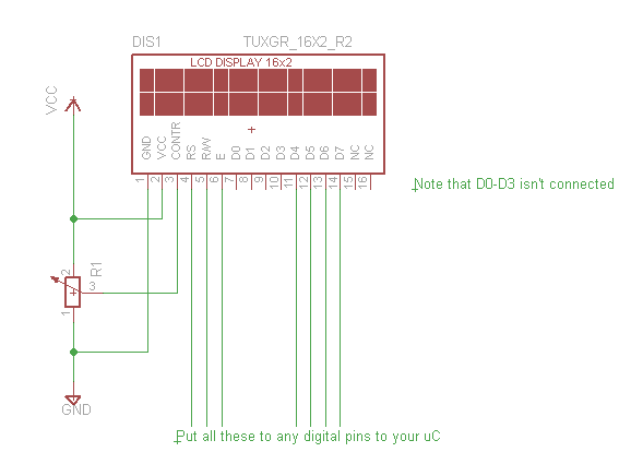
So first thing we want to do is to understand the functions of the PINS. For original description please refer to page 8 in datasheet.
| Pin | Function |
| RS |
Selects registers. |
| R/W |
Selects read or write. |
| E | Starts data read/write. |
| DB4 to DB7 |
Four high order bidirectional tristate data bus |
| Contr | Regulate the contrast of the display |
I will elaborate on the pins as we go on. The main thing is to understand briefly more or less what they are for. Even though when we will be reading the instruction sheet, you'll see that the datasheet already provides which control pins you have to set HIGH and which LOW. So don't worry about it so much.
Registers
Refer to page 9 for original description.
Basically the HD44780 consists of two main 8-bit registers for controlling the LCD. IR - instruction register; DR - data register.
As the names already suggest instruction register will be accessed for configuring and writing instructions to the LCD. DR register on the other hand will be used for writing the data you want for the display to show (not exactly accurate). You can see DR register as a buffer between two RAMs. It's a temporary register which will eventually write itself automatically in of the available RAMs - CGRAM or DDRAM, depending on what you have written in IR.
DDRAM is used to temporary store the characters the display will show. So by changing the DDRAM, you will write text on your display. DDRAM stores the characters, how they will be drawn, depending on the code (page 10). You have the ability to put like 8 custom characters in CGRAM, but I won't be elaborating on that. Actually, that would be a good homework. Try to read the datasheet and improve my code to support custom characters. It's not that hard believe me.
For more detailed description refer to datasheet.
Busy flag (BF)
Basically a busy flag is an indicator that the data from DR register is being written to one of the RAMs. You don't want to change your data until it has finished writing it to the LCD. Otherwise the data will be corrupt and you end up showing Japanese characters (maybe). Basically the pin D7 is the busy flag, while it logic HIGH it means the data is being written to the LCD, when it's 0 obviouslly it's not busy anymore.
Address Counter (AC)
Address counter is basically a register, which specifies which block of RAM you want to either read or write to the LCD. It applies to both of the RAMs - DDRAM and CGRAM. While configuring the device, we will be able to set AC to be incremented or decremented automatically, so for most cases you won't need to worry about it. Until we get to assigning coordinates where the text should be written.
Display Data RAM (DDRAM)
I already briefly described the function of DDRAM. If you missed it, it's for storing the data which is currently displayed on the LCD.
But there is one important thing which I want to elaborate on, I even got confused on this matter. Basically the datasheet will tell you that there it has two modes 1-line display and 2-line display. From our perspective I have 4 line display, so how come there isn't 4-line display available for DDRAM?
It's because the LCD actually acts as 2-line display, to make it more confusing they alternate. See the picture below:
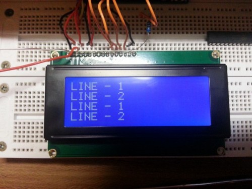
Technically Line 1 is one line in DDRAM and Line 2 as well.
So we need to make some kind of line mapping.
In DDRAM Line 1 starts at address 0x00 and technically finishes at 0x3F. At the end of 3rd line on real display.
I don't want to elaborate more on these confusing lines, just see the picture below with the starting addresses of each line:
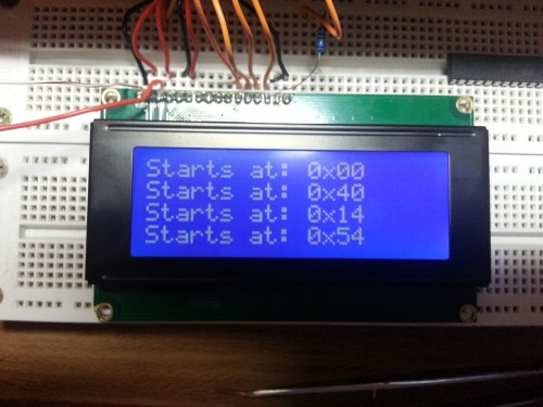
So how did I come up with those numbers. We know that HD44780 can hold up to 80 characters in DDRAM, also we know that 1st line and 2nd line acts as a single 40 character line. It means that when we write 20th character on line 1 it will be 3rd line on the real device. Then just by adding 20, we can get each of the starting addresses.
Can you tell me what is the final address in DDRAM?
So far we have covered the main structure of the HD44780 LCD driver. You should now have an intuition of how the data is passed around and how it is stored. For CGRAM, you'll have figure that on your own. Believe me it's not that hard.
Writing the code
Hopefully, we are now ready to write the code for Arduino.
First thing we want to do is to initialize the display. Please see the Figure 24 on page 46 in datasheet. It has a nice diagram for the initialization.
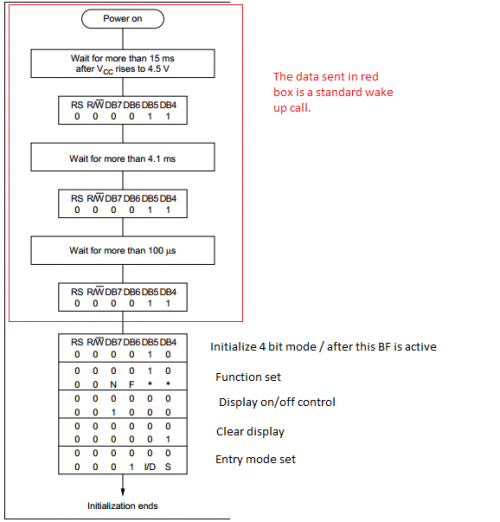
Note: As you can see in the diagram above, after we have initialized 4 bit mode, the following data will be sent in two blocks. 1. we send the upper bits and the lower one. I will elaborate how to do it later on, but for now think of them as a single byte. For example, function set will be 0010 NF00.
Function set
In function set we basically configure how many line the display has and the size of the character blocks.
N = 0: 1 line display
N = 1: 2 line display
F = 0: 5x8 character size (most common)
F = 1: a bigger character size, can't seem to find the exact size in datasheet. You will just have to take my word
So for my setup, I'll need N = 1 and F = 0. So the byte I'll send would be 0x28 (0010 1000)
Display on/off control
It' s basically instruction to enable/disable the display, to show/hide the cursor and to make the cursor blink. Please refer to page 28 in datasheet.
As you can see it has 3 bits called D, C and B. Those are for configuring the things I mentioned before. But for initializition, we just turn off the display.
Clear display
I think this is self explanatory, the instruction is mentioned as well in page 28.
Entry mode
Final step you have to take to initialize the display. Basically in entry mode you configure whether the address counter (AC) will increment or decrement automatically and whether the display will shift instead of the cursor.
AS you can see in the diagram it has two bits I/D and S. If you want to know exactly how you can configure them, refer to page 26 in datasheet.
However, I configure them as I/D = 1 and S = 0. Which means, AC will be incremented automatically and the display will not be shifted.
One more thing
At this point we kind of have initialized the display, however we have to turn on the display. So after this, we have to call another Display on/off control instruction, this time we want to switch it on. And if you want for debugging or any other reason, you can enable now the cursor and the blinking of the cursor as well.
In my case I just enabled the display, I don't want to see the cursor. Taking account all my preferences I have to send this byte: 0x0C
Let's write the C code
So now we know exactly what we have to do to initialize the LCD. I think it's time to write a simple function to do it.
void SimpleLCD::lcdInit()
{
  //Set all the control pins to logic Zero
  digitalWrite(_RS, 0);
  digitalWrite(_RW, 0);
  digitalWrite(_E, 0);


  //Do the wake up call
  delay(20);
  sendCommand(0x30);
  delay(20);
  sendCommand(0x30);
  delay(20);
  sendCommand(0x30);
  delay(20);
  sendCommand(0x20);  //Let's make it 4 bit mode
  delay(10);
  //That's it LCD is initialized in 4 bit mode.


  sendCommand4Bit(0x28); //N = 1 (2 line display) F = 0 (5x8 characters)
  sendCommand4Bit(0x08); //Display on/off control D=0,C=0, B=0
  sendCommand4Bit(0x01); //Clear Display
  sendCommand4Bit(0x06); //Entry mode set - I/D = 1 (increment cursor) & S = 0 (no shift)
  sendCommand4Bit(0x0C); //Display on/off control. D = 1, C and B = 0. (Cursor and blink, last two bits)
}
You probably noticed I'm using some new functions. Both of those we have to write on our own.
So the first function sendCommand, is for sending 8 bits in parallel. I couldn't figure out how to merge with 4 bit function, because it is slightly different.
Anyway, remember at the beginning I was describing how the data is sent to the HD44780. Just enable the pins D7-D4 pins accordingly, either wait for busy flag or for couple ms. Taking into account what I now said, we can construct a simple code for sending a byte
void SimpleLCD::sendCommand(char opCode)
{
  digitalWrite(_D4, opCode & 0x10);
  digitalWrite(_D5, opCode & 0x20);
  digitalWrite(_D6, opCode & 0x40);
  digitalWrite(_D7, opCode & 0x80);
}
Now we have to construct a function which will allow us to send a byte in two blocks. Important is to remember what is shown in figure 9 on page 22. is to trigger the enable pin E, when we have data ready to be sent. It has to be twice, since we are sending the upper bits and the lower bits.
void SimpleLCD::sendCommand4Bit(char opCode)
{
  digitalWrite(_D4, opCode & 0x10);
  digitalWrite(_D5, opCode & 0x20);
  digitalWrite(_D6, opCode & 0x40);
  digitalWrite(_D7, opCode & 0x80);
  digitalWrite(_E,HIGH);
  digitalWrite(_E,LOW);
  digitalWrite(_D4, opCode & 0x01);
  digitalWrite(_D5, opCode & 0x02);
  digitalWrite(_D6, opCode & 0x04);
  digitalWrite(_D7, opCode & 0x08);
  digitalWrite(_E,HIGH);
  digitalWrite(_E,LOW);
  lcdBusy();
}
Remember, I was writing that you have to wait until the data is written in the RAM, either you substitute the lcdBusy() function for something like delay(1) or let's write a function for checking the busy flag. See page 24 in datasheet, what command we have to send to read the busy flag, and which bit we will have to read.
So from the datasheet, we can see that we have to set RS to 0 and R/W to 1, and the BF is located on pin DB7. Taking all that into account, we can now write a function to wait until LCD has finished writing data to RAM. Another thing, because we are using 4 bits, we have to trigger the enable pin to read the upper 4 bits and then lower 4 bits. since we are only interested in BF for now, we can make a dummy trigger.
void SimpleLCD::lcdBusy()
{
  digitalWrite(_RS, LOW);
  pinMode(_D7, INPUT);
  digitalWrite(_RW, HIGH);

  int busyFlag = 1;
  while(busyFlag == 1)
  {
    //The data should be read while Enable pin is HIGH
    digitalWrite(_E, HIGH);
           busyFlag = digitalRead(_D7);
    digitalWrite(_E, LOW);

    //Clock out the lower part of data, since we are interested in only the
    //upper part. more precissaley D7 pin.
    digitalWrite(_E, HIGH);
    digitalWrite(_E, LOW);
  }
  pinMode(_D7, OUTPUT);
  digitalWrite(_RW, LOW);
}
Basically those are all the necessary functions to communicate with the LCD. Now just to simplify our life, we can write a function to send string of characters automatically. I like to send a pointer to the string of characters and then just increment it until we reach the end. Just see my code you'll understand.
void SimpleLCD::lcdWriteText(char *text)
{

   while( *text)
   {
               digitalWrite(_RS,HIGH);
       sendCommand4Bit(*text++);
   }
}
Now you should be able to send text in a very user friendly manner. It probably would be a good idea to implement a way to move the cursor around the screen. See page 24 in datasheet, on how to set CGRAM address.
void SimpleLCD::lcdGoToAddr(char addr)
{
    char cmd = 0x80 | addr;
    digitalWrite(_RS, LOW);
    digitalWrite(_RW, LOW);
    sendCommand4Bit(cmd);
}
Okay, now we have the ability to move the cursor by specifying it's address. However, it is not very user friendly, it would be easier for a programmer to be able to write XY coordinates rather than CGRAM address. So let's make a coordinate mapping function.
void SimpleLCD::lcdGoToXY(char x, char y)
{
  char addr;
  switch(x)
  {
     case 0: addr = 0x00; break; //Starting address of 1st line
     case 1: addr = 0x40; break; //Starting address of 2nd line
     case 2: addr = 0x14; break; //Starting address of 3rd line
     case 3: addr = 0x54; break; //Starting address of 4th line
     default: ;
  }

  addr +=y;

  lcdGoToAddr(addr);
}
And that's it! You have implemented all the basic functions to use a 20x4 HD44780 based character LCD display. I wrote a simple class like library for the arduino.
You can see it below:
SimpleLCD.h
/*
  SimpleLCD.h - Library for interfacing 20x4 LCD character display.
  Created by Raivis Strogonovs, August 6, 2013.
  Released into the public domain.
*/
#ifndef SimpleLCD_h
#define SimpleLCD_h

#include "Arduino.h"


class SimpleLCD
{
  public:
    SimpleLCD(int RS, int RW, int E, int D4, int D5, int D6, int D7);
    void lcdGoToXY(char x, char y);
    void lcdGoToAddr(char addr);
    void lcdInit();
    void lcdClear();
    void lcdWriteText(char *text);
    void lcdBusy();
    void sendCommand(char opCode);
    void sendCommand4Bit(char opCode);

  private:
    int _RS;
    int _RW;
    int _E;
    int _D4;
    int _D5;
    int _D6;
    int _D7;
};

#endif
SimpleLCD.cpp
/*
  SimpleLCD.h - Library for interfacing 20x4 LCD character display.
  Created by Raivis Strogonovs, August 6, 2013.
  Released into the public domain.
*/

#include "Arduino.h"
#include "SimpleLCD.h"

SimpleLCD::SimpleLCD(int RS, int RW, int E, int D4, int D5, int D6, int D7)
{
    _RS = RS; _RW = RW; _E = E;
    _D4 = D4; _D5 = D5; _D6 = D6; _D7 = D7;

    pinMode(_RS, OUTPUT);
    pinMode(_RW, OUTPUT);
    pinMode(_E, OUTPUT);
    pinMode(_D4, OUTPUT);
    pinMode(_D5, OUTPUT);
    pinMode(_D6, OUTPUT);
    pinMode(_D7, OUTPUT);
}

void SimpleLCD::lcdGoToXY(char x, char y)
{
  char addr;
  switch(x)
  {
     case 0: addr = 0x00; break; //Starting address of 1st line
     case 1: addr = 0x40; break; //Starting address of 2nd line
     case 2: addr = 0x14; break; //Starting address of 3rd line
     case 3: addr = 0x54; break; //Starting address of 4th line
     default: ;
  }

  addr +=y;

  lcdGoToAddr(addr);
}

void SimpleLCD::lcdGoToAddr(char addr)
{
    char cmd = 0x80 | addr;
    digitalWrite(_RS, LOW);
    digitalWrite(_RW, LOW);
    sendCommand4Bit(cmd);
}

void SimpleLCD::lcdInit()
{
  //Set all the control pins to logic Zero
  digitalWrite(_RS, 0);
  digitalWrite(_RW, 0);
  digitalWrite(_E, 0);


  //Do the wake up call
  delay(20);
  sendCommand(0x30);
  delay(20);
  sendCommand(0x30);
  delay(20);
  sendCommand(0x30);
  delay(20);
  sendCommand(0x20);  //Let's make it 4 bit mode
  delay(10);
  //That's it LCD is initialized in 4 bit mode.


  sendCommand4Bit(0x28); //N = 1 (2 line display) F = 0 (5x8 characters)
  sendCommand4Bit(0x08); //Display on/off control D=0,C=0, B=0
  sendCommand4Bit(0x01); //Clear Display
  sendCommand4Bit(0x06); //Entry mode set - I/D = 1 (increment cursor) & S = 0 (no shift)
  sendCommand4Bit(0x0C); //Display on/off control. D = 1, C and B = 0. (Cursor and blink, last two bits)
}

void SimpleLCD::lcdClear()
{
   digitalWrite(_RS, LOW);
   digitalWrite(_RW, LOW);
   sendCommand4Bit(0x01);
}

 void SimpleLCD::lcdWriteText(char *text)
 {

    while( *text)
    {
                digitalWrite(_RS,HIGH);
        sendCommand4Bit(*text++);
    }
 }

void SimpleLCD::lcdBusy()
{
  digitalWrite(_RS, LOW);
  pinMode(_D7, INPUT);
  digitalWrite(_RW, HIGH);

  int busyFlag = 1;
  while(busyFlag == 1)
  {
    //The data should be read while Enable pin is HIGH
    digitalWrite(_E, HIGH);
           busyFlag = digitalRead(_D7);
    digitalWrite(_E, LOW);

    //Clock out the lower part of data, since we are interested in only the
    //upper part. more precissaley D7 pin.
    digitalWrite(_E, HIGH);
    digitalWrite(_E, LOW);
  }
  pinMode(_D7, OUTPUT);
  digitalWrite(_RW, LOW);
}

void SimpleLCD::sendCommand(char opCode)
{
  digitalWrite(_D4, opCode & 0x10);
  digitalWrite(_D5, opCode & 0x20);
  digitalWrite(_D6, opCode & 0x40);
  digitalWrite(_D7, opCode & 0x80);
}

void SimpleLCD::sendCommand4Bit(char opCode)
{
  digitalWrite(_D4, opCode & 0x10);
  digitalWrite(_D5, opCode & 0x20);
  digitalWrite(_D6, opCode & 0x40);
  digitalWrite(_D7, opCode & 0x80);
  digitalWrite(_E,HIGH);
  digitalWrite(_E,LOW);
  digitalWrite(_D4, opCode & 0x01);
  digitalWrite(_D5, opCode & 0x02);
  digitalWrite(_D6, opCode & 0x04);
  digitalWrite(_D7, opCode & 0x08);
  digitalWrite(_E,HIGH);
  digitalWrite(_E,LOW);
  lcdBusy();
}
So the usage of this class would be as follows:
Simple example how to use the code.
#include "SimpleLCD.h";
const int backlightPin = 11;
const int RS = 3;
const int RW = 4;
const int E = 5;
const int D4 = 6;
const int D5 = 7;
const int D6 = 8;
const int D7 = 9;
SimpleLCD lcd(RS,RW,E,D4,D5,D6,D7);
int lcdBrightness = 255;
int incomingByte = 0;
void setup() {
Serial.begin(9600);
// set the digital pin as output:
pinMode(backlightPin, OUTPUT);
digitalWrite(backlightPin, HIGH);
lcd.lcdInit();
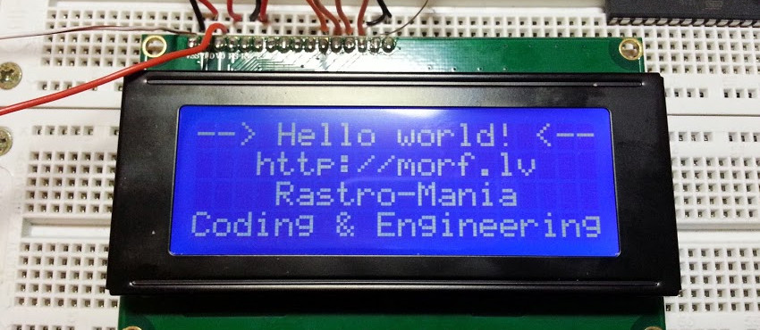
lcd.lcdWriteText("--> Hello world! <--");
lcd.lcdGoToXY(1,3);
lcd.lcdWriteText("https://morf.lv");
lcd.lcdGoToXY(2,4);
lcd.lcdWriteText("Rastro-Mania");
lcd.lcdGoToXY(3,0);
lcd.lcdWriteText("Coding & Engineering");
}
void loop()
{
if (Serial.available() > 0)
{
// read the incoming byte:
incomingByte = Serial.read();
if(incomingByte == 'h')
{
if(lcdBrightness < 255)
lcdBrightness+=17;
analogWrite(backlightPin,lcdBrightness);
}
else if(incomingByte == 'l')
{
if(lcdBrightness > 0)
lcdBrightness-=17;
analogWrite(backlightPin,lcdBrightness);
}
else if(incomingByte == 'c')
{
lcd.lcdClear();
}
// say what you got:
Serial.print("LCD brightness: ");
Serial.println(lcdBrightness, DEC);
}
}
Download: SimpleLCD.zip (2.53K)
That's all folks! Hopefully, I was descriptive enough, so you can understand how the character LCD displays are interfaced. Keep on learning.