I and my friend Zenios Agapiou thought of constructing a simple two wheel balancer robot. At the beginning we thought we will just program our Atmega88pa micro-controller through standard JTAG. However, we quickly realized we have Bluetooth connected to the RX/TX device, so we thought whether we can upload Arduino bootloader to the atmega and program it wirelessly. However it wasn’t that simple as we initially anticipated.
Thanks Hackaday for publishing this article
First challenge, which wasn’t big of a challenge, was to get the Arduino bootloader on atmega88p. More precisely we used Optiboot, since they claim it to be the quarter of size of the original bootloader. However, it doesn’t come precompiled for atmega88p, but only for atmega88. Basically, their signatures don’t match, other than that they are identical. So we just added atmega88p to the Makefile and to the code as well in optiboot.c and pin_defs.h files.
All in all, the compiling and installation of bootloader was the simplest part of the project. What we didn’t realize that Arduino does hardware reset when someone connects to the serial port to boot in bootloader. Now we had to figure out a way to boot in the bootloader when someone connects to the serial port, also we had to find a way HOW to detect that someone connected to the Bluetooth HC-06.
The HC-06 is very basic and limited Bluetooth adapter with SPP (serial port profile) on it. The default firmware is limited to only changing baudrate, name, pin code and that’s it. Reprogramming the HC-06 was out of the question. However, we quickly noticed that the status LED on the Bluetooth is blinking when nobody is connected, and it stops flashing when there is a connection established. Basically, we thought of using the LED to detect whether someone is connected or not, now we only had to find a quick way of detecting whether the LED is flashing or not. Initially we thought we can just do it with a simple RC circuit. Unfortunately, we quickly found out that ONLY RC circuit won’t be able to produce enough difference for the micro-controller to read when to reset or a monostable to activate.
We set our selves a constraint that we must find a way to detect the state with the tools and ICs which are available around the house. Since we are still studying engineering, we had some OP-AMPS lying around, and we could construct a simple differential amplifier.
So the final circuit would consist of RC circuit to basically low pass filter the LED signal and a differential amplifier so we can easily determine whether someone is connect or not.
The RC stage
The values for RC circuit we basically just guessed. Even though, we did some minor calculations. In our design we are using 6.8k resistor and 10uF capacitor which gives us time constant of 68ms. From our measurements we know that the LED is blinking in ~5Hz
See below the LED signal and the LOW pass filtered signal:
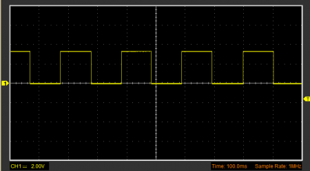
Blinking LED
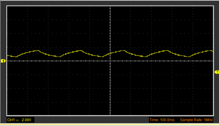
Low pass filtered LED blinking.
The differential amplifier stage
The second part of the circuit was to get the differential amplifier producing readable logic HIGH and logic LOW. Note, we our logic circuit is powered in 3.3V, and according to datasheet 0.2*VCC is logic zero and 0.7*VCC is logic HIGH.
So according from the measurements after low pass filter, in worst case scenario we would have to amplify difference of 0.587 V (3.3V – 2.713 V) to at least above 2.31V (0.7 * 3.3). We don’t mind saturation, so we will just make sure worst case scenario is in logic HIGH levels.
Considering the information above, we decided to configure the gain of differential amplifier to 4.7, basically we used 1M and 4.7M resistors. Anyway as you can see in the figure below, when LED is blinking we produce constant voltage over 2.31V.
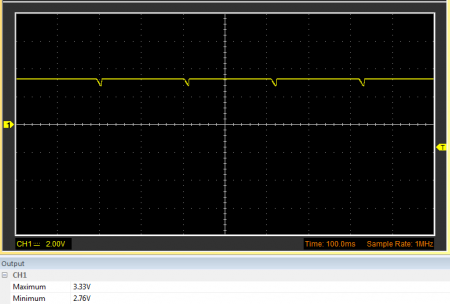
Output of the system when nobody is connected to Bluetooth
When someone connects to the Bluetooth, eventually the output will be ~0V, so there is nothing interesting to show from oscilloscope.
See the final circuit of the system below:
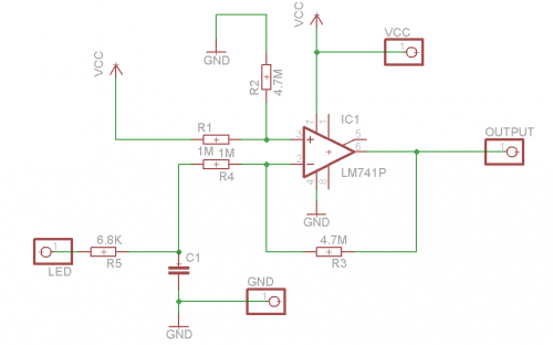
Final circuit of the system, we did not use LM741, we just put it in the circuit diagram because it has the same pinout with OPA241PA. It won’t work with LM741, because of its properties when it comes to saturation.
Hacking the bootloader
Little did we know that producing reliable logic HIGH and LOW from the Bluetooth will be half battle. Note that to reset the micro-controller we used external interrupt, detecting falling edge and then starting watchdog timer.
There were two problems when it came to resetting the micro-controller via watchdog.
- The bootloader detects, that it was reset via watchdog and immidiatly goes back to application
- If the micro was reset at the wrong time, it will go back to main application.
First we “fixed” the bootloader not to reset when watchdog triggers a reset. Basically, the bootloader checks MCUSR register for EXTRF flag. We just changed that to our own “doReset” flag.
// Adaboot no-wait mod
ch = MCUSR;
MCUSR = 0;
if (!(ch & _BV(EXTRF))) appStart(ch);
Original code
ch = MCUSR;
MCUSR = 0;
if(doReset == 1) appStart(ch);

doReset = 1;
Our modified code
Obviously we lose the ability to go back quickly to the main application when watchdog was initiated. For us, it’s not a big loss.
At this stage we had another problem, when initiating the programming, most of the times AVR-DUDE would produce out of sync error. After some Googling, we found out that the reset apparently must be done at the right time, otherwise it would just go back to main application. We weren’t satisfied with such bootloader and went back to the code, to see whether we can “improve” the bootloader.
To see exactly what AVR-DUDE is sending, we just set verbosity to 4, and found out that the AVR-DUDE first sends 0x30, waits for response and then sends 0x20. Which means STK_GET_SYNC and CRC_EOP accordingly. After following the bootloader, we found out that, if it receives 0x20 first, it will go to “verifySpace ()”, which in turn will check if it receives “0x20”, since he went to the function with 0x20, it would receive 0x30 next and instead will go to main application immediately.
Lucky for us AVR-DUDE apparently tries 3 times to send 0x30 and then 0x20. So we had to make sure, that in the beginning first thing bootloader receives is 0x30. To do so we just added simple while loop before the main “for” loop to make sure it continues only when it receives 0x30. Like so:
ch = getch();
while(ch != 0x30)
{
    ch = getch();
}
  /* Forever loop */
  for (;;) {
.......
And that solved our synchronizing issues. We can now easily program the micro-controller even by just manually pressing the reset button, it doesn’t need to be in correct time, the bootloader will make sure now that it will enter the main loop when the correct value has been received at the beginning.
Obviously we lose the ability to go back quickly to the main application when watchdog was initiated. For us, it’s not a big loss.
Also we initiate reset in the micro-controller as follows:
int main()
{
        EICRA |= (1<<ISC11) | (0<< ISC10);
    EIMSK|= (1<<INT1);
    DDRB |= (1<<PORTB5);
    sei();
}

ISR(INT1_VECT)
{
        wdt_reset();
    wdt_enable(WDTO_15MS);
    while(1);
}
It is mandatory to put this code in any of the application using our programming system to do automatic reset, otherwise to program; the device has to be reset by hand.
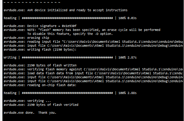
Avr-dude output when programming via Bluetooth, better check the video below
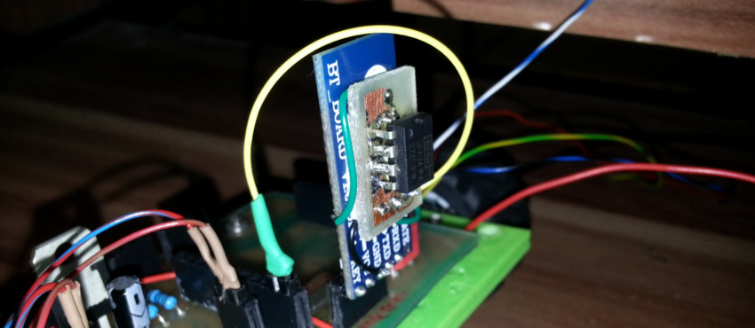
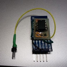
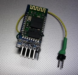
Some pictures of the setup.
Obviously, we can further improve the system, by using monostable to trigger the reset button. But that involves buying parts, since we don’t have any monostables lying around, and designing one around 555 would make the circuit big
Download the sample code, eagle project and modified Optiboot here:
Download: bluetooth_programmer.zip (154.96K)