Parallel to my work, I always do some kind of project every summer. Last summer was a game, which I didn’t manage to finish (got lazy on designing the levels). However, this summer I took on to a journey in a field I have almost no experience. Basically, I built my own 3D printer. Without any kits, I wanted to take away from this journey as much as I could. I’ll try to remember all I did, and write as detailed as possible about this journey. In any case, I would advise anyone to try and do this project, it’s a very good learning experience, but be warned that it isn’t a walk in a park, like I thought. When I started this project, I though it wouldn’t take more than 2 weeks to finish it. Well if you know what you are doing, probably it would take less than one day to assemble it, but I didn’t.
My own constraints
To get most of this project, and to try to make the printer cheaper, I constrained myself to avoid buying any kits. Well after correcting a lot of mistakes I did along the way; probably it wasn’t much cheaper than a kit.
Here is a small table on how much I spent for individual parts.
|
Item |
Price (GBP) |
|
RepRap M8 / 8mm Stainless Steel Smooth Rods |
27.45 |
|
Reprap 3D Printer Reprap Prusa / Mendel M8 Threaded Bar |
20.29 |
|
Prusa i2 (RepRap) Fasteners, Springs and Bearings |
61.00 |
|
Prusa Mendel i2 Reprap Printed Parts Kit LM8UU 3D Printer +Wades Extruder |
59.99 |
|
Nema17 stepper motors |
62.00 |
|
PSU 500W PC |
15.50 |
|
HotEnd / Hot End EZ s157 for RepRap 3D printers |
33.88 |
|
3D printer, RepRap: Sanguinololu 1.3a electronic controller kit unassembled |
61.95 |
|
3D Printer, RepRap: PCB Heatbed new MK2a for Prusa |
12.99 |
|
MDF 9x9 inch and 6mm thick |
9.70 |
|
Photo frame glass 2mm thick |
5.00 |
|
|
369.75 |
In total I should have spent 369.75 British pounds. However, after correcting my mistakes, I think I spent about 430 pounds. I will write about my mistakes later on, so if anyone is reading this article, can avoid my mistakes, and make his own mistakes.
Of course, the RepRap can be built even cheaper, cheapness, had a big role for me, but not as big, as trying to get most of the project. I could probably make this printer much cheaper, just by going back to my country of origin, where most of the mechanical parts, could be 5x cheaper. In my opinion UK is not very hacker friendly. For god sakes, you can’t easily buy acetone or ethanol. Even when you are buying pair of scissors, they will ask you if you’re 21 or over. I don’t want to bash UK, mostly it’s a great country, only issues I have is not being friendly to tinkerers like me.
Building the printer
First thing I want to tell everyone who will start building the RepRap, is that, if you’re going to build it without kit, get ready to get frustrated. You can easily buy parts from different kits and the documentation for building is incomplete. A lot of times I faced a part, which is not referenced in the documentation and had to figure out where to put it. Not a big deal, but be ready for that. In other words, just don’t get me started on how bad the documentation is. Even X smooth rod length don’t match with the current plastic part, they haven’t updated the wiki for that. Anyway, it will be confusing, but it’s doable.
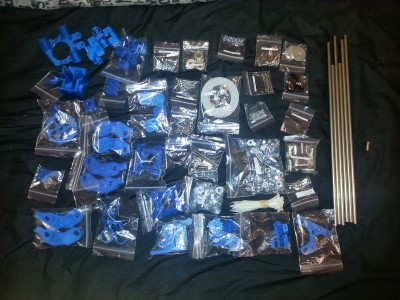
So this is what I started with:
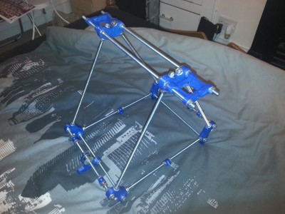
After 20 minutes you can get this:
Oh by the way I wanted to mention instructions I followed to build it. It’s a mix of these 3:
- http://reprap.org/wiki/Prusa_Mendel_Assembly_%28iteration_2%29
- http://reprap.org/wiki/How_to_build_Prusa_2
- http://garyhodgson.com/reprap/prusa-mendel-visual-instructions/ (one of the best)
Well the beginning of this article will be more like a gallery rather than, in depth description. Later on I will state problem I encountered, and how I fixed it.
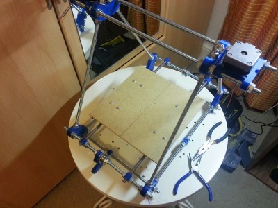
Attaching 6mm thick and 229x229mm MDF bed.
Assembling XZ axis. As you can see, one of the parts is red. Guess what happened? If you guessed it broke, you’re correct. The holes where the smooth rod comes in, is about 4mm smaller than the rod itself. It takes a lot of power to insert them, and I was pushing on the bearing guide, obviously it snapped. So be careful.
Another thing, you can notice, is that the smooth rods go through my blue X bracket, it’s because, I was thinking whether to risk and cut them smaller, or just drill through it. Maybe the mistake wasn’t the fact I drilled through, but I slightly filed the smooth rod holes, so I can insert them more easily, and later when I was printing, I had problems with inconsistent layers, basically the hot-end was fluctuating. I fixed it, by printing myself a new part, where you can fix the rods in place with screws. This is the part I printed to fix my fluctuation. http://www.thingiverse.com/thing:16090
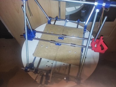
Nothing much to add here, as you can see, I have assembled Y axis and I’ve put on X carriage + heat bed.
In this picture you can see another problem I encountered, with the wonderful Prusa i2 printer. My belt guide wasn’t aligned with the belt pulley. So my solution was to insert couple nuts between the screw and the motor, this worked like a charm.
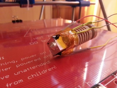
An assembled J-head MkV extruder. Even though I’m not using this one anymore, since someone broke it. I will elaborate on this a little bit later on.
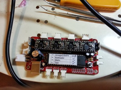
Assembled sanguinololu. It was pain to get the arduino IDE to recognize and upload the firmware. First thing criticism I would say to Arduino developers is that, you should seriously consider backwards compatibility. It’s not a big problem; however, due to lack of backwards compatibility you have to use the old 0.23 arduino IDE to get Sprinter/Marlin firmware running. Note: you have to put the sanguinololu binaries in two places; anyway, for your convenience you can download the IDE here, with sanguinololu binaries included.
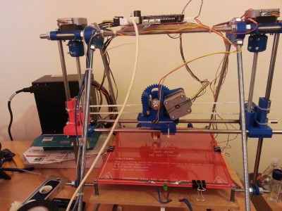
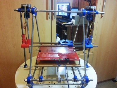
Nearly there, everything has been assembled, extruder, all axis, motors and electronics. It’s time to test the motors.
Here you can see a video of my first big failure. I didn’t know that high voltage stepper motors don’t usually work well with micro-stepping drivers. Well, to fix this issue, you have two options.
- Buy a new PSU, which can provide 24V for the motors, to enable micro-stepping
- Buy new low voltage stepper motors. I chose this one, and gave my high voltage motors to my father.
And don’t forget to adjust the current limit, I forgot and burned two of the pololu stepper drivers!
While I was playing with the motors I accidently burned my PSU as well. Due to failed soldering. Somehow I managed not to solder one of the pins for the LM7805, which was causing many issues, even switching my computer off time to time, when it drew more than 500mA from it.
To convert the ATX PSU for my prusa I watched this video:
Even if you don’t intend to use ATX, I would suggest to watch that video anyway, very useful.
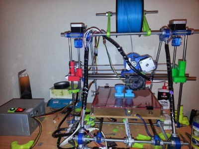
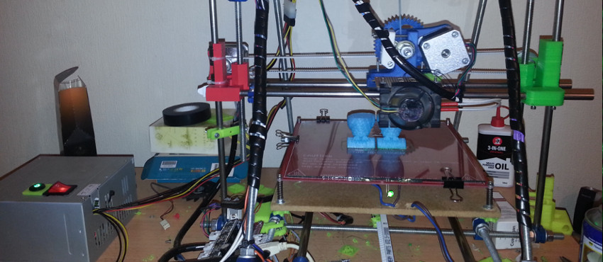
And this is how my printer looks as of now.
If you want the spool holder you can download it here. Even though there were available designs on thingiverse, I thought its easy enough part, to design it on my own.
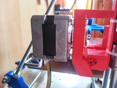
Another problem I encountered was that the XY axis rods were slipping away, since I filed the holes a little bit too much. So I printed a new part, where the XY smooth rods can go through, and they are tightened with 4 screws on the bottom. You can see that part in the previous picture on right side (the green one). I thought it would solve my crappy printing quality, because my XY axis was moving back and forth while going up, when they weren’t tightened. Well I was wrong. Maybe it did improve a little bit. But basically it stayed the same. Then I noticed that actually my hot end is pretty loose and it had free movement of about 5 mm in every direction. So I found a new J-head mounting plate on thingverse http://www.thingiverse.com/thing:26355
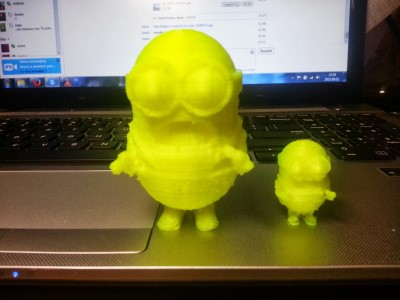
IT has one drawback, it’s about 5 mm thick, and so I lost some printing height. But on the other hand, the quality now is amazing. You can barely feel the layers, without smoothing with acetone or anything; it feels like a top quality part. Now I’m satisfied with the quality. See pictures below:
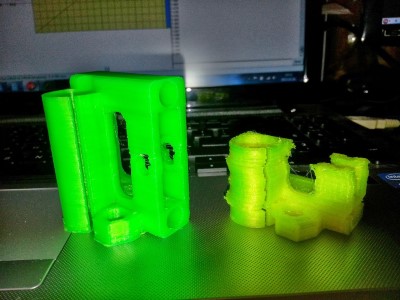
The green parts are with the new j-head mounting plate.
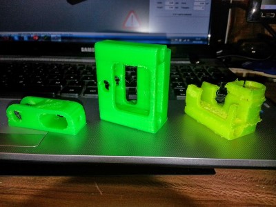
Here are some prints I’ve done with the previous mounting plate.
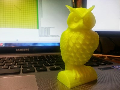
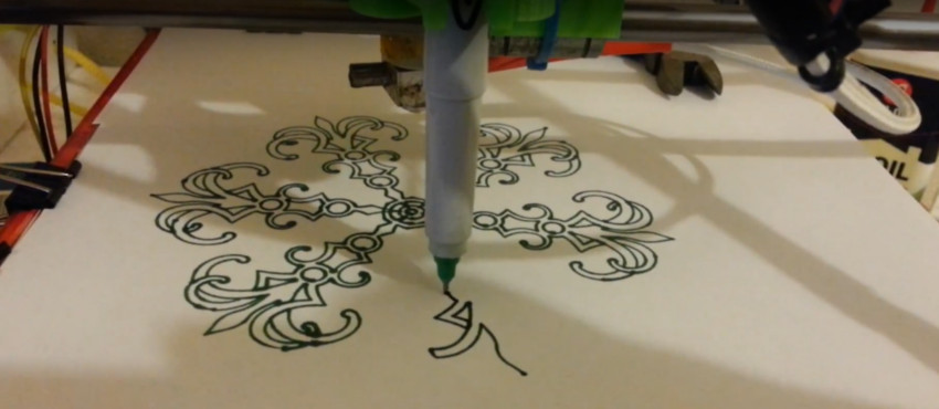
Here you can see my 3D printer printing the owl you see above:
Conclusion
One thing for sure, I learned a lot when building my own 3D printer. Before I barely know anything about mechanics, now I have some intuition about how stuff works and how I would design a mechanic device. I would suggest building a 3D printer on their own to anyone who wants to get challenged and learn in the process.
Just remembered another thing, when I had problems with PLA sticking to the bed, I noticed, that was because I was cleaning the bed with pure acetone. It’s much better using a nail polisher with acetone and glycerin, sticks like a rock, haven’t had warped parts for couple of weeks now.