For me, one of the first things I wanted to test is how to setup the system clock. In this tutorial I'll be explaining how to set up external oscillator from 8-16Mhz and how to set up the xmega to use internal 32MHz clock. I think, by providing instructions for these two types of system clocks, anyone should be able to understand the logic behind the datasheet and set up whichever clock he/she wants.
Introduction
There is one notable difference between setting system clock in xmega compared to mega series. The system clock in xmega is set in run-time, basically in code itself, instead of rewriting fuses. Many times I've accidently written incorrect fuses in the micro.
By default and on every reset the xmega's clock will be reset back to 2MHz internal clock. And the system clock can be changed during normal operation at any time.
You have following options, when choosing clock source (datasheet page 96):
- Internal oscillators
- 32kHz ultra low power oscillator
- 32.768 kHz calibrated oscillator
- 32MHz run-time calibrated oscillator
- 8MHz calibrated oscillator
- External clock source
- 0.4 MHz - 16MHz crystal oscillator
- External clock input
- 32.768 kHz crystal oscillator
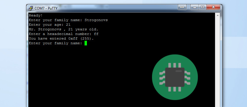
In this tutorial I'll be describing how to set up internal 32MHz oscillator, without external clock calibration. And I'll show how to set up external crystal oscillator. Personally I think I'll be using them the most. If you need very precise 32MHz clock you should consider reading page 99 in datasheet about digital frequency locked loop (DFLL). Remember, that you'll need to put 32.768kHz external clock to do DFLL. But from my tests, internal 32MHz clock is precise enough for 115200 baudrate for USART. So far I haven't had any problems with data being corrupted.
0.4 MHz - 16MHz crystal oscillator
When setting up external oscillator first you have to write in XOSCTRL resgister information about your crystal. The frequency range and the start up time. For basic usage, you just need to concentrate on two configuration group bits - FRQRANGE and XOSCSEL
By looking at the two tables below you should select those two group of bits according to your crystal:
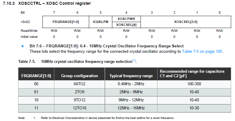
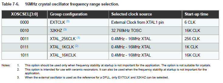
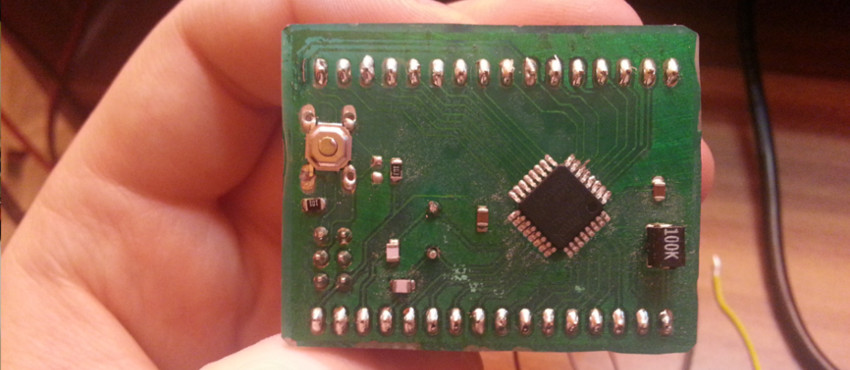
In my case, more specific in case of my breakout board which I wrote about before, I had a 16MHz crystal, so by following the first table I should configure the bits FRAQRANGE to 11 and from my past experience the slowest boot up time is always the most reliable. So for XOSCSEL bits I just select 1011.
So I end up configuring my XOSCCTRL with following value: 0b11001011.
In the code, due to Atmel providing mapping you can write the same value in a more user firendly way:
OSC_XOSCCTRL = OSC_FRQRANGE_12TO16_gc | OSC_XOSCSEL_XTAL_16KCLK_gc;
Note: XOSCCTRL is an artifical subregister of OSC register.
After we have configured what external crystal we will be using in OSC_CTRL register we need to enable external crystal. See table 7.13, you'll see that external oscillator enable bit called "XOSCEN" is bit 3 in the OSC_CTRL register.
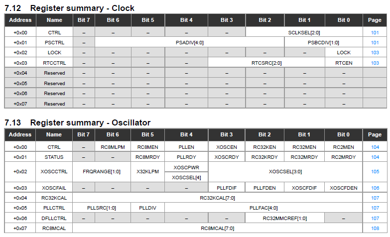
More details about the individual bits in OSC_CTRL register see datasheet page 104
After we have enable our external crystal a good approach would be to wait the clock to stabalize. As you can see in table 7.13, there is a register called STATUS, basically the name is self explanotary. The register holds whether a particular clock has stabilized or not. If it has stabilizied, the corresponding bit will bit set to HIGH. In our case we are interested in XOSCRDY bit, which checks whether external clock has stabilized.
The check itself is quite forward, just loop until XOSCRDY is set to high.
//Enable external oscillator
OSC_CTRL |= OSC_XOSCEN_bm;
//Wait for clock stabilization
while(!(OSC_STATUS & OSC_XOSCRDY_bm));
We are almost done, however after initializing the oscillator, we have to trigger Configuration change protection mechanism (CCP) and it 4 clock cycles change the CLOCK CTRL multiplexer to use the external clock. For more detailed explenation, please refer to page 13 in datasheet. So as I mentioned before we have to select external clock in CLK_CTRL register, with bits SCLKSEL. Please see table below of the possible configuration for system clock:
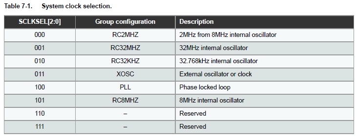
Obviously accroding to the table 7-1, in our case we have to set those bits to 011. But again, atmel prvoides us to do it in user friendly way, like this:
CCP = CCP_IOREG_gc;
CLK_CTRL = CLK_SCLKSEL_XOSC_gc;
And that's it, by following the steps I took above you should have come up with a code similar to this:
void setUp16MhzExternalOsc()
{
        //16MHz external crystal
        OSC_XOSCCTRL = OSC_FRQRANGE_12TO16_gc | OSC_XOSCSEL_XTAL_16KCLK_gc;
        //Enable external oscillator
        OSC_CTRL |= OSC_XOSCEN_bm;
        //Wait for clock stabilization
        while(!(OSC_STATUS & OSC_XOSCRDY_bm));
        // Selects clock system as external clock
        // through change protection mechanism
        CCP = CCP_IOREG_gc;
        CLK_CTRL = CLK_SCLKSEL_XOSC_gc;
}
You can call the method above anytime you want in your code to switch to 16Mhz external clock, obviously I normally do it at the very begining of my main function.
32MHz run-time calibrated oscillator
Setting up the 32MHz clock without the DFLL is actually easier. I have yet to check the DFLL so I am not able to comment on this. But even without DFLL the 32MHz for my purpose works without any problem.
Basically to enable the 32MHz internal clock we just have to enable bit RC32MEN and wait for the internal clock to stabilize. Then the system clock source slection process with CCP is the same, only difference is that, according to the table 7-1 we have to set SCLKSEL bits to 001.
I'm not going to elaborate more on this, because it will essentially be the same for external crystal.
The setup function should look something like this:
void setUp32MhzInternalOsc()
{
    OSC_CTRL |= OSC_RC32MEN_bm; //Setup 32Mhz crystal

    while(!(OSC_STATUS & OSC_RC32MRDY_bm));

    CCP = CCP_IOREG_gc; //Trigger protection mechanism
    CLK_CTRL = CLK_SCLKSEL_RC32M_gc; //Enable internal  32Mhz crystal


}
A full example should look similar to this:
void setUp16MhzExternalOsc()
{
        PORTD_DIR = 0x01;
        //16MHz external crystal
        OSC_XOSCCTRL = OSC_FRQRANGE_12TO16_gc | OSC_XOSCSEL_XTAL_16KCLK_gc;
        //Enable external oscillator
        OSC_CTRL |= OSC_XOSCEN_bm;
        //Wait for clock stabilization
        while(!(OSC_STATUS & OSC_XOSCRDY_bm));
        // Selects clock system as external clock
        // through change protection mechanism
        CCP = CCP_IOREG_gc;
        CLK_CTRL = CLK_SCLKSEL_XOSC_gc;
}

void setUp32MhzInternalOsc()
{
    OSC_CTRL |= OSC_RC32MEN_bm; //Setup 32Mhz crystal

    while(!(OSC_STATUS & OSC_RC32MRDY_bm));

    CCP = CCP_IOREG_gc; //Trigger protection mechanism
    CLK_CTRL = CLK_SCLKSEL_RC32M_gc; //Enable internal  32Mhz crystal


}

int main(void)
{


    //setUp16MhzExternalOsc();
    setUp32MhzInternalOsc();


    PORTA_DIR = 0xff;


    while(1)
    {
        PORTA_OUT = ~PORTA_OUT;
    _delay_us(50);

    }
}
References
Atmel. (2013). XMEGA E MANUAL. Available: http://www.atmel.com/Images/Atmel-42005-8-and-16-bit-AVR-Microcontrollers-XMEGA-E_Manual.pdf. Last accessed 08/03/2014.